Download
1 / 37
370 likes | 574 Vues
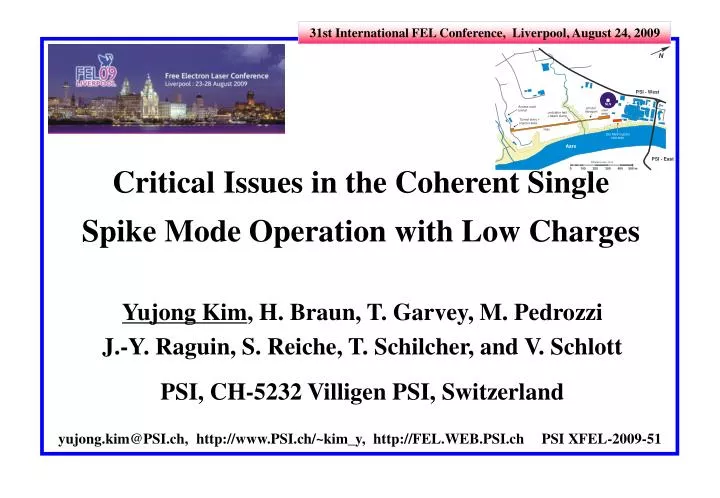
31st International FEL Conference, Liverpool, August 24, 2009. Critical Issues in the Coherent Single Spike Mode Operation with Low Charges. Yujong Kim , H. Braun, T. Garvey, M. Pedrozzi J.-Y. Raguin, S. Reiche, T. Schilcher, and V. Schlott PSI, CH-5232 Villigen PSI, Switzerland.

E N D
31st International FEL Conference, Liverpool, August 24, 2009 Critical Issues in the Coherent Single Spike Mode Operation with Low Charges Yujong Kim, H. Braun, T. Garvey, M. Pedrozzi J.-Y. Raguin, S. Reiche, T. Schilcher, and V. Schlott PSI, CH-5232 Villigen PSI, Switzerland PSI XFEL-2009-51 yujong.kim@PSI.ch, http://www.PSI.ch/~kim_y, http://FEL.WEB.PSI.ch
Outline • Acknowledgments • Introduction to the SwissFEL Project • Limited Site and Operation Modes • Optimized Injector for Various Single Bunch Charges • Single Spike Mode Operation with 2 pC for XFEL @ 0.1 nm • Nominal and Single Spike Mode Operations with 10 pC for XFEL @ 0.7 nm • Critical Issues in Single Spike Mode Operation with Low Charges • Tight RF Jitter Tolerances • Random CSR Kicking and Orbit Fluctuation • Wavelength or Bunch Length, Charge, Beam Diagnostics • Energy Chirp and Wide Bandwidth • Summary Yujong Kim for the Ultra-Compact X-ray FEL Project - SwissFEL
Acknowledgements Y. Kim sincerely give thank to following persons: - K. Floettmann of DESY - M. Borland of ANL - Y. Ding, J. Frisch, D. Dowell, and P. Emma of SLAC - J.B. Rosenzweig and C. Pellegrini of UCLA for valuable discussions, helpful information, and encouragements on this work! 3 3 Yujong Kim for the Ultra-Compact X-ray FEL Project - SwissFEL
SwissFEL - Limited Site 2008-2014 : 250 MeV Injector Test Facility - Commissioning will be started in October, 2009 2012-2016 : RF Gun + Short C-band Linac + In-Vacuum Undulator based 5.8 GeVSwissFEL Facility initial (2016-2020) operation modes : 100 Hz with two micro-bunches (0.1 nm to 7 nm) upgrade (after 2020) : 400 Hz with three bunches + longitudinal single spike mode (0.7 nm to 7 nm) total facility length < 800 m undulator length < 70 m total available length for linac < 530 m See details from our talks and posters : MOPC05 : seeding MOPC06 : EEHG seeding @ 250 MeV injector MOPC07 : low charge operation MOPC36 : projected emittance measurement method MOPC62 : transverse beam size effects in OTR spectrum MOPC63 : gun laser MOPC64 : chirp and bandwidth control with C-band linac MOPC65 : THz pump source TUPC35 : commissioning results of Low Emittance Gun phase-II (LEG-II) TUPC36 : advanced beam diagnostic section TUPC37 : design concepts of compact SwissFELlinac TUPC38 : construction status and overview of 250 MeV injector test facility WEPC58 : tolerance study hard X-ray beamline THOA01 : undulators for the SwissFEL PSI - West available site length 950 m LEG Test Facility SwissFEL Facility 4 Yujong Kim for the Ultra-Compact X-ray FEL Project - SwissFEL
SwissFEL - Required Parameters & Modes To get saturation at 1 Å with 5.8 GeV (or 7 Å with 3.4 GeV) with ~ 50 m undulator. †assumed in-vacuum (NdFeB with diffused dy) undulator parameters: K = 1.2, λu= 15 mm, <β> = 15 m, total length ~ 70 m for 1 Å higher ρshorter LG Yujong Kim for the Ultra-Compact X-ray FEL Project - SwissFEL
SwissFEL - 250 MeV Injector Test Facility Commissioning will be started in November 2009 6 6 6 Yujong Kim for the Ultra-Compact X-ray FEL Project - SwissFEL
SwissFEL - Summary of Optimized Injector ASTRA Simulation Results : CTF3 RF Gun based Injector for various Charges Q laser length (FWHM) Ipeak, cathode laser σx,or yεthermalεslice/εprojected 200 pC 9.9 ps22 A 270 µm 0.195 µm 0.320/0.350 µm 150 pC 9.0 ps 18 A 245 µm 0.177 µm 0.272/0.283 µm 100 pC 7.9 ps 14 A 214 µm 0.155 µm 0.220/0.233 µm 50 pC 6.2 ps 8.7 A 170 µm 0.123 µm 0.160/0.174 µm 20 pC 4.6 ps 4.7 A 125 µm 0.091 µm0.108/0.122 µm 10 pC 3.7 ps 3.0 A 100 µm 0.072 µm0.080/0.096 µm 5 pC 2.9 ps 1.9 A 79 µm 0.057 µm 0.062/0.074 µm 2 pC 2.1 ps 1.0 A 58 µm 0.042 µm 0.044/0.054 µm ~ 2 times brighter Final beam parameters are at the exit of the 2nd S-band structure (130 MeV - 172 MeV). Gun max gradient = 100 MV/m, assumed Kave = 0.4 eV. For only Q 2 pC, εprojected εslice εthermal For a much higher Q, εprojected εsliceεthermal due to the nonlinear space charge force. We can get an excellent emittance with a lower charge for the single spike mode operation! 7 7 7 Yujong Kim for the Ultra-Compact X-ray FEL Project - SwissFEL
Full Coherent Single Spike Mode Re-studied - J.B. Rosenzweig et al., NIMA 593 (2008) 39 temporal profile of FEL photon for 3 different bunch lengths Shot-to-shot fluctuation in saturation length due to shot noise startup. Here they assumed that there is no error or jitter in linac. z ~ 0.3 fs for 1 Å z ~ 2 fs for 7 Å for the SwissFEL project due to many difficulties (diagnostics, RF tolerances), we chose 7 Å and higher charge of 10 pC. 8 8 8 Yujong Kim for the Ultra-Compact X-ray FEL Project - SwissFEL
Single Spike with 2 pC - Dancing Bunch For 0.1 nm with 2 pC, if tolerances is loose, operation becomes really unstable: gun timing error ≤ 10 fs (rms) bunch charge error ≤ 0.5% (rms) injector S-band RF phase error ≤ 0.02 deg (rms) injector S-band RF voltage error ≤ 0.02% (rms) injector X-band RF phase error ≤ 0.04 deg (rms) injector X-band RF voltage error ≤ 0.04% (rms) BC1 & BC2 dipole power supply error ≤ 10.0 ppm (rms) LINAC1 S-band RF phase error per klystron ≤ 0.02 deg (rms) LINAC1 S-band RF voltage error per klystron ≤ 0.02% (rms) LINAC2 S-band RF phase error per klystron ≤ 0.02 deg (rms) LINAC2 S-band RF voltage error per klystron ≤ 0.02% (rms) very dynamic peak current & slice parameters! Loose Tolerances for 2 pC under loose tolerances for 2 pC, we performed 300 times start-to-end simulations to see the fluctuation of the longitudinal phase space at the entrance of undulator. beam chirp and position are very dynamically dancing ! under this situation, peak current, beam arrival time, and slice beam parameters are also very dynamically dancing, which induce unstable XFEL photon beams. ~ 100 fs 9 9 9 9 9 9 Yujong Kim for the Ultra-Compact X-ray FEL Project - SwissFEL
Single Spike with 2 pC - More Stabilized For 0.1 nm with 2 pC, we need much more tighter tolerances for stable operation: gun timing error ≤ 1 fs (rms) bunch charge error ≤ 0.5% (rms) injector S-band RF phase error ≤ 0.001 deg (rms) injector S-band RF voltage error ≤ 0.001% (rms) injector X-band RF phase error ≤ 0.004 deg (rms) injector X-band RF voltage error ≤ 0.004% (rms) BC1 & BC2 dipole power supply error ≤ 1.0 ppm (rms) LINAC1 S-band RF phase error per klystron ≤ 0.001 deg (rms) LINAC1 S-band RF voltage error per klystron ≤ 0.001% (rms) LINAC2 S-band RF phase error per klystron ≤ 0.001 deg (rms) LINAC2 S-band RF voltage error per klystron ≤ 0.001% (rms) Ultra-Tight Tolerances for 2 pC under tighter tolerances for 2 pC, we performed 300 times start-to-end simulations to see the fluctuation of the longitudinal phase space at the entrance of undulator. beam position dancing was reduced and chirp dancing was dramatically damped. under this situation, peak current and slice parameters are almost constant. Therefore, XFEL power becomes more stable. But there is some small fluctuation in beam arrival time. ~ 40 fs 10 10 10 10 10 10 10 Yujong Kim for the Ultra-Compact X-ray FEL Project - SwissFEL
SwissFEL - Layouts for 200 pC and 2 pC ASTRA up to exit of SB02 & ELEGANT from exit of SB02 to consider space chare, CSR, ISR, and wakefields ! 72 times brighter Optimization-XIV with C-band RF Linacs for Effective Chirp Control & 400 Hz New Injector Layout with Laser Heater & BC1 @ ~ 450 MeV vertical chirping in single spike mode gives big impacts on current, power, & bandwidth! Optimization-VIII with New Injector for 2 pC Single Spike Mode due to many difficulties, we gave up single spike mode with 2 pC for 0.1 nm! 11 11 Yujong Kim for the Ultra-Compact X-ray FEL Project - SwissFEL
SwissFEL - Two Layouts for 10 pC New Injector Layout with Laser Heater & BC1 @ ~ 450 MeV E = 5800 MeV, = 0.052% x = 8.5 m, y = 8.5 m, z = 1.87 m nx ~ 0.106 m, ny ~ 0.097 m Ipeak < 728 A, n,core,slice < 0.079 m dE,slice < 220 keV for whole bunch 4 times brighter Optimization-X with New Injector for 10 pC Nominal Mode E = 5800 MeV, = 0.053% x = 13.0 m, y = 13.0 m, z = 0.72 m nx ~ 0.240 m, ny ~ 0.097 m Ipeak < 7 kA, n,core,slice < 0.150 m dE,slice < 800 keV for whole bunch Optimization-XI with New Injector for 10 pC Single Spike Mode 12 Yujong Kim for the Ultra-Compact X-ray FEL Project - SwissFEL
SwissFEL - Operation Modes with 10 pC Even Q and Ipk are different, saturation length is shorter than 50 m for (0.7 nm to 7 nm)! Nominal Mode FEL photon beam for Optimization-X rms photon pulse length ~ 2.27 fs wavelength = 0.7 nm with K = 1.05 rms bandwidth ~ 0.08% for 0.7 kA pulse energy ~ 6 µJ no of photon per pulse ~ 2.0×10¹⁰ saturation length ~ 49.7 m for 0.7 kA electron beam for Optimization-X nominal mode beam energy ~ 3.4 GeV Q = 10 pC peak current ~ 0.7 kA rms electron bunch length ~ 6.2 fs total compression factor = 240 FEL photon beam for Optimization-XI rms photon pulse length ~ 250 as wavelength = 0.7 nm with K = 1.05 rms bandwidth ~ 0.35% for 7 kA pulse energy ~ 9 µJ no of photon per pulse ~ 3.1×10¹⁰ saturation length ~ 25 m for 7 kA Single Spike electron beam for Optimization-XI single spike mode (0.7 nm ~ 7 nm) beam energy ~ 3.4 GeV Q = 10 pC peak current ~ 7 kA rms electron bunch length ~ 2.4 fs total compression factor = 2400 13 13 Yujong Kim for the Ultra-Compact X-ray FEL Project - SwissFEL
Nominal Mode with 10 pC - Requirements parameters requirements gun laser arrival timing error ≤ 5 fs (rms) single bunch charge error ≤ 1% (rms) injector S-band phase error per klystron ≤ 0.01 deg (rms) injector S-band voltage error per klystron ≤ 0.01% (rms) injector X-band phase error per klystron ≤ 0.06 deg (rms) injector X-band voltage error per klystron ≤ 0.06% (rms) gun solenoid misalignment after BBA ≤ 20 µm (zero-to-max) S-band structure misalignment after BBA ≤ 100 µm (zero-to-max) S-band solenoid misalignment after BBA ≤ 50 µm (zero-to-max) X-band structure misalignment after BBA ≤ 50 µm (zero-to-max) BC dipole misalignments after BBA ≤ 50 µm (zero-to-max) BC dipole role error after BBA ≤ 25 µrad (zero-to-max) Linac BPM and QM offset (= BBA resolution) ≤ 2 µm (rms) screen spatial resolution to detect 5% emittance growth ≤ 2 µm (zero-to-max) gun solenoid power supply error dI/I ≤ 10 ppm (rms) BC dipole power supply error dI/I ≤ 10 ppm (rms) QM power supply error dI/I ≤ 10 ppm (rms) steerer power supply error dI/I ≤ 10 ppm (rms) girder vibration for 2 Hz to 100 Hz ≤ 50 nm (rms) Undulator BPM resolution 0.85 µm (rms) Tolerance Goal Tarrival 30 fs (zero-to-max) Psat/Psat 30% (zero-to-max) / 0.001% (zero-to-max) Lsat/Lsat 15% (zero-to-max) from 80% core slices Note that the total S-band and X-band klystrons in injector linac are six and two, respectively. Here we assumed that orbit feedback system is working in estimating RF tolerances. 14 14 14 14 14 14 Yujong Kim for the Ultra-Compact X-ray FEL Project - SwissFEL
Single Spike with 10 pC - Requirements For stable coherent single spike mode (0.7 nm to 7 nm) with 10 pC, 3.4 GeV beam. parameters tolerance (rms) tolerance source gun laser arrival timing error ≤ 1 fs (rms) saturation length, arrival time single bunch charge error ≤ 1% (rms) saturation power injector S-band RF phase error per klystron ≤ 0.005 deg (rms) power, wavelength, arrival time injector S-band RF voltage error per klystron ≤ 0.005% (rms) arrival time injector X-band RF phase error per klystron ≤ 0.005 deg (rms) power, saturation length injector X-band RF voltage error per klystron ≤ 0.025% (rms) arrival time BC1 dipole power supply error ≤ 7.5 ppm (rms) arrival time LINAC1 S-band RF phase error per klystron ≤ 0.015 deg (rms) wavelength, power LINAC1 S-band RF voltage error per klystron ≤ 0.010% (rms) wavelength, arrival time BC2 dipole power supply error ≤ 7.5 ppm (rms) arrival time LINAC2 S-band RF phase error per klystron ≤ 0.017 deg (rms) wavelength LINAC2 S-band RF voltage error per klystron ≤ 0.011% (rms) wavelength • beam arrival time error Tarrival 5 fs (zero-to-max) ~ electron bunch length order. • saturation power error Psat/Psat 100% (zero-to-max) against any optics damage. • wavelength error / 0.01% (zero-to-max) against intensity lowering due to collimator. • saturation length error Lsat/Lsat 15% (zero-to-max) to get saturation with a given undulator length • (undulator length margin ~ 30-40%). • Note that the total S-band and X-band klystrons in injector linac are six and six, respectively. • Here we assumed that orbit feedback system is working in estimating RF tolerances. 15 15 15 15 15 Yujong Kim for the Ultra-Compact X-ray FEL Project - SwissFEL
Single Spike with 10 pC - Performance median : ~ 1.0 µs rms variation : ~ 5.5 fs median : ~ 83 GW (80% core slices) rms variation : ~ 86% still some fluctuation when we include all errors together! from 300 times S2E simulations under RF jitter tolerances median : ~ 20 m rms variation : ~ 4.5% median : ~ 1 nm rms variation : ~ 0.006% 16 16 16 16 16 Yujong Kim for the Ultra-Compact X-ray FEL Project - SwissFEL
Single Spike with 10 pC - Performance median : ~ 3.4 GeV rms variation : ~ 0.003% median : ~ 0.69 µm rms variation : ~ 6.5% small but gives a big impact in current due vertical chirping in single spike mode from 300 times S2E simulations under RF jitter tolerances median : ~ 0.109 µm rms variation : ~ 3% median : ~ 9.1e4 rms variaiton : ~ 2.1e-4% 17 17 17 17 17 Yujong Kim for the Ultra-Compact X-ray FEL Project - SwissFEL
Single Spike with 10 pC - CSR Orbit Kicking Under RF jitter tolerances, random RF jitters generates random CSR orbit kicking in the horizontal plan. There is no good way to compensate it because the CSR orbit kicking is random. Since its rms orbit fluctuation is larger than 100% of electron rms beamsize in undulator, there is a big impact on FEL lasing. 300 S2E simulations with RF Jitter Tolerances: electron rms beam size in undulator ~ 13 µm can we get stable lasing?, maybe, no. change error ≤ 1% (rms) laser arrival timing error ≤ 20 fs (rms) injector S-band RF phase error ≤ 0.04 deg (rms) injector S-band RF voltage error ≤ 0.04% (rms) injector X-band RF phase error ≤ 0.16 deg (rms) injector X-band RF voltage error ≤ 0.16% (rms) BC power supply error ≤ 10 ppm (rms) 18 18 18 18 18 Yujong Kim for the Ultra-Compact X-ray FEL Project - SwissFEL
Single Spike with 10 pC - CSR Orbit Kicking Under RF jitter tolerances, random RF jitters generates random CSR orbit kicking in the horizontal plan. There is no good way to compensate it because the CSR orbit kicking is random. Since its rms orbit fluctuation is close to 100% of electron rms beamsize in undulator, there is some impact on FEL lasing. 300 S2E simulations with Required Tolerances: electron rms beam size in undulator ~ 13 µm can we get stable lasing?, maybe, some lasing. change error ≤ 1% (rms) laser arrival timing error ≤ 1 fs (rms) injector S-band RF phase error ≤ 0.005 deg (rms) injector S-band RF voltage error ≤ 0.005% (rms) injector X-band RF phase error ≤ 0.005deg (rms) injector X-band RF voltage error ≤ 0.025% (rms) BC power supply error ≤ 7.5 ppm (rms) 19 19 19 19 19 19 Yujong Kim for the Ultra-Compact X-ray FEL Project - SwissFEL
Nominal Mode with 10 pC - CSR Orbit Kicking Under same RF jitter tolerances for the single spike mode with 10 pC, we checked status of CSR kicking for the nominal mode with 10 pC.Clearly, its CSR orbit kicking is ignorable during the nominal mode, and lasing will be OK. median : ~ 2.5 GW (80% core slices) rms variation : ~ 5% very stable saturation power! 300 S2E simulations with Required Tolerances: electron rms beam size in undulator ~ 8.5 µm can we get stable lasing?, certainly, good lasing. change error ≤ 1% (rms) laser arrival timing error ≤ 1 fs (rms) injector S-band RF phase error ≤ 0.005 deg (rms) injector S-band RF voltage error ≤ 0.005% (rms) injector X-band RF phase error ≤ 0.005deg (rms) injector X-band RF voltage error ≤ 0.025% (rms) BC power supply error ≤ 7.5 ppm (rms) 20 20 20 20 20 20 Yujong Kim for the Ultra-Compact X-ray FEL Project - SwissFEL
Other Issues and Summary By the help of the excellent emittance and higher beam brightness, we can use a low charge to generate the fully coherent single spike at X-ray region. But to realize the single spike mode, we have to carefully choose wavelength or bunch length, and single bunch charge after considering RF tolerances, CSR orbit kicking, and beam diagnostics. Bandwidth of the single spike mode is always wide due to the vertical energy chirp. We expect that the single spike mode will be easy at a longer wavelength (≥ 1 nm) due to is loose RF tolerance and a longer bunch length. PSI chose the single spike mode with 10 pC as an upgraded mode and we will continuously try to find the best wavelength or bunch length and charge to relax RF tolerances. It seems that current LCLS 20 pC operation is between our nominal mode and the single spike mode, which CSR kicking is controllable. And RF tolerances of LCLS is somewhat looser than other compact XFEL projects because there are much more RF stations in LCLS linac. 21 Yujong Kim for the Ultra-Compact X-ray FEL Project - SwissFEL
Appendix 22 Yujong Kim for the Ultra-Compact X-ray FEL Project - SwissFEL
250 MeV Injector Test Facility Parameters 10 pC 100 pC 200 pC laser diameter on cathode 400 µm 857 µm 1080 µm laser pulse length (FWHM) 3.7 ps 7.9 ps 9.9 ps peak current on cathode 3 A 14 A 22 A thermal emittance on cathode 0.072 µm 0.155 µm 0.195 µm core slice emittance before / after BC 0.078 µm / 0.078 µm 0.213 µm / 0.213 µm 0.320 µm / 0.330 µm projected emittance before BC 0.095 µm 0.233 µm 0.350 µm bunch length before BC (rms) 1.05 ps 2.23 ps 2.80 ps bunch length after BC (rms) 33.2 fs 117.6 fs 193.3 fs peak current after BC 104 A 285 A 352 A x / y projected emittance after BC 0.104 µm / 0.096 µm 0.268 µm / 0.233 µm 0.379 µm / 0.350 µm arrival error for stable seeding at ~ 160 nm ~ 5.5 fs ~ 19.6 fs ~ 32.2 fs min beam size on OTRs in 3FODO (rms) ~ 14 µm ~ 35 µm ~ 55 µm 23 23 23 23 Yujong Kim for the Ultra-Compact X-ray FEL Project - SwissFEL
Used Thermal Emittance LCLS Core Slice Emittance Measurements: Q = 20 pC, E ~ 135 MeV Method = QM scan with LOLA E = 135 MeV Q = 20 pC Ecathode ~ 115 MV/m laser = 253 nm (= 4.899 eV) ΔTlaser~ 3.8 ps (FWHM) Laser profile = pseudo-Gaussian shape σz ~ 1.3 ps Ipeak ~ 5 A P. Emma, XFEL2008 Workshop, Courtesy of D. Dowell Simulations for Gun Comparison 0.91 µm/mm PSI LEG-I Measurement 0.61 µm/mm LCLS & PSI LEG-II Measured Core Slice Emittance old CTF3 Simulation 0.72 µm/mm D. Dowell calculated thermal emittance line (0.5 μm/mm) Kave = 0.4 eV was used for our old CTF3 RF gun based injector optimizations! Kave = 0.63 eV was used for our four RF gun based injector optimization (in this talk)! 24 Yujong Kim for the Ultra-Compact X-ray FEL Project - SwissFEL
Optimized Injector for 2 pC CTF3 RF Gun may generate an ultra-low emittance < 0.06 µm for 2 pC ! 25 Yujong Kim for the Ultra-Compact X-ray FEL Project - SwissFEL
Optimized Injector for 2 pC for 2 pC, slice & projected emittances ~ εth = 0.042 µm εnsc contribution to εsliceis ignorable ! Projected Emittance along Injector Slice Emittance at 172 MeV INSB01-RAC INSB02-RAC GUN εprojected = 0.054 µm εslice = 0.044 µm CTF3 RF Gun may generate an ultra-low emittance < 0.06 µm for 2 pC ! 26 26 Yujong Kim for the Ultra-Compact X-ray FEL Project - SwissFEL
2 pC - 300 S2E Simulations For 0.1 nm with 2 pC, if tolerances is loose, operation becomes really unstable: gun timing error ≤ 10 fs (rms) bunch charge error ≤ 0.5% (rms) injector S-band RF phase error ≤ 0.02 deg (rms) injector S-band RF voltage error ≤ 0.02% (rms) injector X-band RF phase error ≤ 0.04 deg (rms) injector X-band RF voltage error ≤ 0.04% (rms) BC1 & BC2 dipole power supply error ≤ 10.0 ppm (rms) LINAC1 S-band RF phase error per klystron ≤ 0.02 deg (rms) LINAC1 S-band RF voltage error per klystron ≤ 0.02% (rms) LINAC2 S-band RF phase error per klystron ≤ 0.02 deg (rms) LINAC2 S-band RF voltage error per klystron ≤ 0.02% (rms) Note that tolerances above are better than current LCLS situation (phase ~ 0.04 deg, dV/V ~ 0.04%) in S-band. Loose Tolerances for 2 pC S03 X01 BC1 LINAC1 BC2 LINAC2 5.8 GeV for 0.1 nm with 2 pC 27 27 27 27 27 27 Yujong Kim for the Ultra-Compact X-ray FEL Project - SwissFEL
2 pC - 300 S2E Simulations median : ~ 1.5 µs rms variation : ~ 16 fs median : ~ 13 GW (80% core slices) rms variation : ~ 130% with loose tolerances, power fluctuation is very strong. poor performance with loose tolerances to generate single spike at 0.1 nm with 2 pC! median : ~ 19 m rms variation : ~ 12% median : ~ 0.1 nm rms variation : ~ 0.008% 28 28 28 28 28 28 28 28 Yujong Kim for the Ultra-Compact X-ray FEL Project - SwissFEL
2 pC - 300 S2E Simulations For 0.1 nm with 2 pC, we need much more tighter tolerances for stable operation: gun timing error ≤ 1 fs (rms) bunch charge error ≤ 0.5% (rms) injector S-band RF phase error ≤ 0.001 deg (rms) injector S-band RF voltage error ≤ 0.001% (rms) injector X-band RF phase error ≤ 0.004 deg (rms) injector X-band RF voltage error ≤ 0.004% (rms) BC1 & BC2 dipole power supply error ≤ 1.0 ppm (rms) LINAC1 S-band RF phase error per klystron ≤ 0.001 deg (rms) LINAC1 S-band RF voltage error per klystron ≤ 0.001% (rms) LINAC2 S-band RF phase error per klystron ≤ 0.001 deg (rms) LINAC2 S-band RF voltage error per klystron ≤ 0.001% (rms) Ultra-Tight Tolerances for 2 pC S03 X01 BC1 LINAC1 BC2 LINAC2 5.8 GeV for 0.1 nm with 2 pC 29 29 29 29 29 29 Yujong Kim for the Ultra-Compact X-ray FEL Project - SwissFEL
2 pC - 300 S2E Simulations median : ~ 1.5 µs rms variation : ~ 4.5 fs median : ~ 13 GW (80% core slices) rms variation : ~ 12% with tighter tolerances, fluctuation is damped. great performance but ultra-tight tolerances! we will not use 2 pC to generate single spike ! median : ~ 19 m rms variation : ~ 3.9% median : ~ 0.1 nm rms variation : ~ 0.001% 30 30 30 30 30 30 30 Yujong Kim for the Ultra-Compact X-ray FEL Project - SwissFEL
Optimized Injector for 10 pC ASTRA Simulation Results with Space Charge CTF3 RF Gun may generate a low emittance < 0.1 µm for 10 pC ! After considering targeting slice emittance (~ 0.18 µm) at the end of linac, we chose thermal emittance ~ 0.072 µm & a low peak current of 3 A at the cathode. 31 31 31 Yujong Kim for the Ultra-Compact X-ray FEL Project - SwissFEL
Optimized Injector for 10 pC Projected Emittance along Injector Slice Emittance at 167 MeV INSB01-RAC INSB02-RAC GUN Excellent Slice Emittance ! And Wide Uniform Range ! Good Invariant Envelope Matching ! Emittance Damping in Booster Linac ! Mismatching Parameter ζ at 167 MeV Q = 10 pC E = 167.654 MeV, = 0.021% x= 105 m, y= 105 m, z = 316 m nx= 0.095 m, ny= 0.095 m Ipeak ~ 3 A, n,core,slice ~ 0.078 m Excellent Projected & Slice Emittance ! Excellent Uniformity in Current Profile ! Better Twiss Mismatching Parameter ! 32 32 32 Yujong Kim for the Ultra-Compact X-ray FEL Project - SwissFEL
Efforts on Chirp & Bandwidth From our recent full S2E simulations with ASTRA, ELEGANT, and GENESIS codes (Y. Kim and S. Reiche), we confirmed that we can effectively minimize the bandwidth of XFEL photon beams by optimizing energy chirping of electron beams. Optimization-III & V S-band based Linacs Linac Length = 650 m Optimization-VI & VII C-band based Linacs Linac Length = 540 m, 510 m Optimization-V chirp for Ipk = 2.7 kA Optimization-III, VI, VII chirp for Ipk = 1.6 kA Saturation Length < 50 m !!! wavelength = 0.1 nm @ FEL1 no of photon per pulse ~ 1.0×10¹¹ saturation length ~ 40 m with 2.7 kA saturation length ~ 48 m with 1.6 kA BW ~ 0.1% for Ipk = 2.7 kA BW ~ 0.05% for Ipk = 1.6 kA 33 33 Yujong Kim for the Ultra-Compact X-ray FEL Project - SwissFEL
SwissFEL - RF Development Milestone year requirements compression factor operation conditions 2010 ϕs 0.1 deg (rms) 1 for injector gun V/V 0.1% (rms) with 22 A, 200 pC 2011 ϕs 0.06 deg (rms) 16 for injector BC1 V/V 0.06% (rms) with 350 A, 200 pC 2012 ϕs 0.04 deg (rms) 75 for XFEL BC1+BC2 V/V 0.04% (rms) with 1.6 kA, 200 pC 2014 ϕs 0.02 deg (rms) 125 for XFEL BC1+BC2 V/V 0.02% (rms) with 2.7 kA, 200 pC 2016 ϕs 0.01 deg (rms) 240 for XFEL BC1+BC2 V/V 0.01% (rms) with 0.7 kA, 10 pC after 2020 ϕs 0.005 deg (rms) 2400 for XFEL BC1+BC2 V/V 0.005% (rms) with 7 kA, 10 pC These are requirements for S-band RF for about 1 minute. Requirements of X-band are four times of S-band. 34 for LCLS 1 nC case Nominal Operation Modes 90 for LCLS 250 pC case Upgrade Mode 34 34 34 34 34 34 Yujong Kim for the Ultra-Compact X-ray FEL Project - SwissFEL
10 pC - Criteria of Jitter Tolerance • To determine error tolerances for the single spike mode operation with 10 pC,at the • entrance of undulator (3.4 GeV), following FEL performance should be satisfied • when there is an error in a single machine component: • beam arrival time error Tarrival 5 fs (zero-to-max) ~ electron bunch length order. • saturation power error Psat/Psat 100% (zero-to-max) against any optics damage. • wavelength error / 0.01% (zero-to-max) against intensity lowering due to collimator. • saturation length error Lsat/Lsat 15% (zero-to-max) to get saturation with a given • undulator length (undulator length margin ~ 30-40%). • Please note that in rms (~ zero-to-max/3.0), they are about: • Tarrival 1.7 fs (rms), tighter than European XFEL (12 fs) due to a shorter bunch. • Psat/Psat 33% (rms), looser than European XFEL (5%) • / 0.003% (rms), tighter than European XFEL (0.007%) due to smaller photons • Lsat/Lsat 5% (rms), looser than European XFEL (0.5%) 35 35 35 Yujong Kim for the Ultra-Compact X-ray FEL Project - SwissFEL
Single Spike with 10 pC - Jitter Sensitivity error source : RF phase of S-band linac (S03) in injector error range : -0.06 deg to +0.06 deg with 10 steps monitoring point : at the entrance of undulator @ 3.4 GeV For / 0.01% (zero-to-max), S-band RF phase error 0.005 deg (rms). This S-band RF phase tolerance is challenging ! wavelength change due to 10 S-band phase errors long. phase space & peak current fluctuation due to errors wavelength ~ 1 nm energy ~ 3.4 GeV undulator period = 40 mm beta-function ~ 10 m K ~ 1.6 ~ 30 fs injector S-band RF phase errors and LINAC1 RF phase and voltage errors, and LINAC2 RF phase and voltage errors are sensitive jitter sources to photon beam wavelength. 36 36 36 Yujong Kim for the Ultra-Compact X-ray FEL Project - SwissFEL
Single Spike with 10 pC - Jitter Sensitivity error source : RF voltage of S-band linac (S03) in injector error range : -0.10% to +0.10% with10 steps monitoring point : at the entrance of undulator @ 3.4 GeV For Tarrival 5 fs (zero-to-max), S-band RF voltage error 0.005% (rms). This S-band RF voltage tolerance is challenging ! arrival time change due to 10 S-band voltage errors arrival time fluctuation due to 10 S-band voltage errors ~ 60 fs BC1 chicane power supply error, gun timing error, injector S-band RF voltage and phase errors are sensitive jitter sources to photon beam arrival time. 37 37 37 Yujong Kim for the Ultra-Compact X-ray FEL Project - SwissFEL