Network Optimization Techniques: Minimal Spanning Tree, Maximal Flow & Shortest Route
Learn how to connect points efficiently, calculate maximum flow, and find shortest paths in a network using software tools.

Network Optimization Techniques: Minimal Spanning Tree, Maximal Flow & Shortest Route
E N D
Presentation Transcript
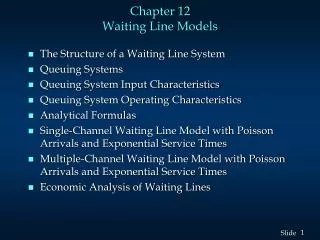
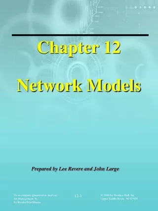
Chapter 12 Network Models 12-1
Learning Objectives Students will be able to • Connect all points of a network while minimizing total distance using the minimal-spanning tree technique. • Determine the maximum flow through a network using the maximal-flow technique. • Find the shortest path through a network using the shortest-route technique. • Understand the important role of software in solving network problems. 12-2
Chapter Outline 12.1 Introduction 12.2 Minimal-Spanning Tree Technique 12.3 Maximal-Flow Technique 12.4 Shortest-Route technique 12-3
Minimal-Spanning Tree Technique • Determines the path through the network that connects all the points while minimizing total distance. 12-4
Minimal-Spanning TreeSteps 1. Select any node in the network. 2. Connect this node to the nearest node that minimizes the total distance. 3. Considering all of the nodes that are now connected, find and connect the nearest node that is not connected. If there is a tie for the nearest node, select one arbitrarily. A tie suggests that there may be more than one optimal solution. 4. Repeat the third step until all nodes are connected. 12-5
Minimal-Spanning TreeLauderdale Construction 3 2 4 5 3 5 3 7 2 7 1 2 3 8 3 5 2 1 6 6 4 12-6
Minimal-Spanning TreeIterations 1&2 3 2 4 5 3 5 3 7 2 7 1 First Iteration 2 3 8 3 5 2 1 6 3 6 4 2 4 5 3 5 3 7 2 7 1 Second Iteration 2 3 8 3 5 2 1 6 6 4 12-7
Minimal-Spanning TreeIterations 3&4 3 2 5 4 3 5 3 7 2 1 7 Third Iteration 2 3 8 3 5 2 1 6 3 6 4 2 5 3 4 3 5 2 7 1 7 2 Fourth Iteration 3 8 3 5 2 1 6 6 4 12-8
Minimal-Spanning TreeIterations 5 & 6 3 2 5 4 3 5 3 7 1 2 7 Fifth Iteration 2 3 8 3 5 2 1 6 6 4 3 2 5 4 3 3 5 7 1 2 7 Sixth iteration 2 3 8 3 5 2 1 6 6 4 12-9
7th Iteration Seventh & final iteration 3 Minimum Distance: 16 2 4 5 3 5 3 7 2 7 1 2 3 8 3 5 2 1 6 6 4 12-10
The Maximal-Flow Technique 1. Pick any path from start (source) to finish (sink) with some flow. If no path with flow exists, then the optimal solution has been found. 2. Find the arc on this path with the smallest capacity available. Call this capacity C. This represents the maximum additional capacity that can be allocated to this route. 3.For each node on this path decrease the flow capacity in the direction of flow by the amount C. For each node on this path, increase the flow capacity in the reverse direction by C 4. Repeat these steps until an increase in flow is no longer possible. 12-11
Maximal-Flow Road Network for Waukesha 2 1 2 1 2 East Point 6 1 3 0 2 1 1 1 West Point 0 10 4 1 6 5 0 1 3 3 2 12-12
Capacity Adjustment Iteration 1 Add 2 2 1 2 2 East Point Subtract 2 6 3 West Point 1 0 3 2 4 East Point 6 1 New path West Point 1 12-13
Maximal-Flow Road Network for Waukesha Add 2 2 1 2 1 2 East Point Subtract 2 6 1 3 0 2 1 1 West Point 0 1 10 4 1 6 5 0 3 1 3 2 Path = 1, 2, 6 12-14
Second Iteration Add 1 0 3 2 1 4 East Point 6 1 1 0 2 1 1 1 West Point 0 10 4 1 Subtract 1 6 5 0 3 1 3 2 12-15
Second Iteration 0 4 2 0 4 East Point 6 2 0 0 2 2 0 1 West Point 0 10 4 1 6 5 0 3 1 3 2 New Path Path = 1, 2, 4, 6 12-16
Third Iteration 0 4 2 0 4 East Point 6 2 0 0 West Point 2 2 0 1 0 4 10 1 Subtract 2 6 5 0 3 1 3 2 Add 2 12-17
Third Iteration 0 4 2 0 4 East Point 6 2 0 2 West Point 2 2 0 1 0 4 10 1 4 5 0 3 3 3 0 New Path Path = 1, 3, 5, 6 12-18
Road Network for WaukeshaThird Iteration 0 4 2 0 4 East Point 6 2 0 West Point 2 2 2 0 1 0 8 4 1 4 Flow (Cars Per Hour) 5 Path 2 3 3 1-2-6 200 3 0 1-2-4-6 100 1-3-5-6 200 Total 500 12-19
The Shortest-Route Technique 1. Find the nearest node to the origin. Put the distance in a box by the node. 2.Find the next nearest node to the origin, and put the distance in a box by the node. In some cases, several paths will have to be checked to find the nearest node. 3. Repeat this process until you have gone through the entire network. The last distance at the ending node will be the distance of the shortest route. You should note that the distances placed in the boxes by each node are the shortest route to this node. These distances are used as intermediate results in finding the next nearest node. 12-20
Shortest-Route ProblemRay Design, Inc. 4 2 200 100 100 100 Plant 150 Warehouse 6 1 50 100 200 40 3 5 Roads from Ray’s Plant to the Warehouse 12-21
Ray Design, Inc.First Iteration 100 2 4 200 100 100 100 Plant 150 Warehouse 1 6 50 200 100 40 3 5 12-22
Ray Design, Inc.Second Iteration 100 2 4 200 100 100 100 Plant 150 Warehouse 1 6 50 200 100 40 3 5 150 12-23
Ray Design, Inc.Third Iteration 100 2 4 200 100 100 100 Plant 150 Warehouse 1 6 50 200 100 40 5 3 150 190 12-24
Ray Design, Inc.Fourth Iteration 100 2 4 200 100 100 290 100 Plant 150 Warehouse 1 6 50 200 100 40 3 5 150 190 12-25