Download
1 / 75
850 likes | 1.44k Vues
Learn the fundamental concepts of antennas, including transmission, reception, polarizations, types, characteristics, and formulas for effective communication technologies. Understand the principles behind radiation and induction fields for optimal signal transmission.

E N D
Basic Antenna Theory and Concepts ICS 620 Communication Technologies Class #11
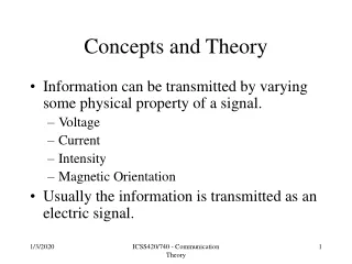
Introduction • An antenna is an electrical conductor or system of conductors • Transmission - radiates electromagnetic energy into space • Reception - collects electromagnetic energy from space • In two-way communication, the same antenna can be used for transmission and reception
Antenna Definition • An antenna is a circuit element that provides a transition form a guided wave on a transmission line to a free space wave and it provides for the collection of electromagnetic energy. Antenna research from Miller & Beasley, 2002
Antenna Definition-cont’d • In transmit systems the RF signal is generated, amplified, modulated and applied to the antenna • In receive systems the antenna collects electromagnetic waves that are “cutting” through the antenna and induce alternating currents that are used by the receiver
Reciprocity • An antenna ability to transfer energy form the atmosphere to its receiver with the same efficiency with which it transfers energy from the transmitter into the atmosphere • Antenna characteristics are essentially the same regardless of whether an antenna is sending or receiving electromagnetic energy
Polarization • Polarization is the direction of the electric field and is the same as the physical attitude of the antenna • A vertical antenna will transmit a vertically polarized wave • The receive and transmit antennas need to possess the same polarization
Types of Antennas • Isotropic antenna (idealized) • Radiates power equally in all directions • Dipole antennas • Half-wave dipole antenna (or Hertz antenna) • Quarter-wave vertical antenna (or Marconi antenna) • Parabolic Reflective Antenna
Directional Antenna beamwidth • A Max power Radiated energy is focused in a specific direction antenna 2 dipole Power 3dB down from maximum point A
Beamwidth • Beamwidth is the angular separation of the half-power points of the radiated pattern
Half-wave Dipole (Hertz) Antenna • An antenna having a physical length that is one-half wavelength of the applied frequency is called a Hertz antenna or a half-wave dipole antenna. Hertz antennas are not found at frequencies below 2MHz because of the physical size needed of the antenna to represent a half-wave
Vertical (Marconi) Antenna • Vertical Antennas are used for frequencies under 2 MHz. It uses a conducting path to ground that acts as ¼ wavelength portion the antenna above the ground. The above ground structure represents a /4 wavelength
Vertical (Marconi) Antenna – cont’d • Poor grounding conditions of the earth/soil surrounding the antenna can result in serious signal attenuation. This problem is alleviated by installing a counterpoise
Counterpoise • Counterpoise is a grounding grid established where the earth grounding cannot satisfy electrical requirements for circuit completion. It is designed to be non-resonant at the operating frequency
Counterpoise-cont’d radius = ¼ antenna supports
Antenna Array • Antenna array is a group of antennas or antenna elements arranged to provide the desired directional characteristics. Generally any combination of elements can form an array. However, equal elements in a regular geometry are usually used.
Yagi-Uda Antenna • The Yagi-Uda antenna is a simple form of a directional antenna based off of a reflector placed /4 from the dipole antenna’s placement. Complex analysis to define the radiated patterns are experimental rather than theoretical calculations
Yagi-Uda Antenna-cont’d reflector /2 /4 dipole antenna
Radiated Directed Signal antenna 2 dipole radiated signal without reflector 2 dipole radiated signal with reflector
The Antenna Formula c 186,000 misec frequency of the signal • c is the speed of light • is the wavelength of the signal • use 3 x 10⁸ when dealing in meters for the speed of light
The Antenna Formula - applied • If a half-wave dipole antenna needed to be constructed for a 60 Hz signal, how large would it need to be? c 186,000 misec = 3100 mi 60 2 = 1550 miles!
Radiation & Induction Fields • The mechanics launching radio frequencies from an antenna are not full understood. The RF fields that are created around the antenna have specific properties that affect the signals transmission. The radiated field field is known as the (surprisingly!) radiation field
Radiation & Induction Fields-cont’d • There are two induction fields or areas where signals collapse and radiate from the antenna. They are known as the near field and far field. The distance that antenna inductance has on the transmitted signal is directly proportional to antenna height and the dimensions of the wave R 2D2
Radiation & Induction Fields-cont’d R 2D2 Where: R = the distance from the antenna D = dimension of the antenna = wavelength of the transmitted signal
Radiation Resistance • Radiation Resistance is the portion of the antenna’s impedance that results in power radiated into space (i.e., the effective resistance that is related to the power radiated by the antenna. Radiation resistance varies with antenna length. Resistance increases as the increases
Effective Radiated Power (ERP) • ERP is the power input value and the gain of the antenna multiplied together • dBi = isotropic radiator gain • dBd = dipole antenna gain
Radiation Pattern • Radiation pattern is an indication of radiated field strength around the antenna. Power radiated from a /2 dipole occurs at right angles to the antenna with no power emitting from the ends of the antenna. Optimum signal strength occurs at right angles or 180° from opposite the antenna
Radiation Patterns • Radiation pattern • Graphical representation of radiation properties of an antenna • Depicted as two-dimensional cross section • Beam width (or half-power beam width) • Measure of directivity of antenna • Reception pattern • Receiving antenna’s equivalent to radiation pattern
Radiation Pattern for Vertical Antennas /4 /2 antenna
Antenna Gain • Antenna gain • Power output, in a particular direction, compared to that produced in any direction by a perfect omnidirectional antenna (isotropic antenna) • Effective area • Related to physical size and shape of antenna
Antenna Gain • Antenna gain is the measure in dB how much more power an antenna will radiate in a certain direction with respect to that which would be radiated by a reference antenna
Antenna Gain • Relationship between antenna gain and effective area • G = antenna gain • Ae= effective area • f = carrier frequency • c = speed of light (» 3 ´ 108 m/s) • = carrier wavelength
Propagation Modes • Ground-wave propagation • Sky-wave propagation • Line-of-sight propagation
Ground Wave Propagation • Follows contour of the earth • Can Propagate considerable distances • Frequencies up to 2 MHz • Example • AM radio
Sky Wave Propagation • Signal reflected from ionized layer of atmosphere back down to earth • Signal can travel a number of hops, back and forth between ionosphere and earth’s surface • Reflection effect caused by refraction • Examples • Amateur radio • CB radio
Line-of-Sight Propagation • Transmitting and receiving antennas must be within line of sight • Satellite communication – signal above 30 MHz not reflected by ionosphere • Ground communication – antennas within effective line of site due to refraction • Refraction – bending of microwaves by the atmosphere • Velocity of electromagnetic wave is a function of the density of the medium • When wave changes medium, speed changes • Wave bends at the boundary between mediums
Line-of-Sight Equations • Optical line of sight • Effective, or radio, line of sight • d = distance between antenna and horizon (km) • h = antenna height (m) • K = adjustment factor to account for refraction, rule of thumb K = 4/3
Line-of-Sight Equations • Maximum distance between two antennas for LOS propagation: • h1 = height of antenna one • h2 = height of antenna two
LOS Wireless Transmission Impairments • Attenuation and attenuation distortion • Free space loss • Noise • Atmospheric absorption • Multipath • Refraction • Thermal noise
Thermal Noise • Thermal noise due to agitation of electrons • Present in all electronic devices and transmission media • Cannot be eliminated • Function of temperature • Particularly significant for satellite communication
Noise Terminology • Intermodulation noise – occurs if signals with different frequencies share the same medium • Interference caused by a signal produced at a frequency that is the sum or difference of original frequencies • Crosstalk – unwanted coupling between signal paths • Impulse noise – irregular pulses or noise spikes • Short duration and of relatively high amplitude • Caused by external electromagnetic disturbances, or faults and flaws in the communications system
Other Impairments • Atmospheric absorption – water vapor and oxygen contribute to attenuation • Multipath – obstacles reflect signals so that multiple copies with varying delays are received • Refraction – bending of radio waves as they propagate through the atmosphere