IP Multicast: Technology and Applications
Explore the world of IP multicast, why it's essential, and the challenges it poses in modern data communication. Learn about IP multicast group addressing, IGMP protocols, multicast routing, and data distribution policies.

IP Multicast: Technology and Applications
E N D
Presentation Transcript
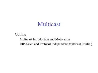
Multicast Outline Multicast Introduction and Motivation DVRMP
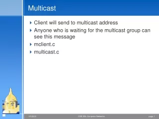
R R S S R R R R One to many communication • Multiple unicasts • IP multicast
Why Multicast? • When sending same data to multiple receivers • Avoid bandwidth bottleneck • Better bandwidth utilization • Application • Video/Audio broadcast (one sender) • Video conferencing (many senders) • Real time news distribution • Interactive gaming
IP multicast service model • Invented by Steve Deering (PhD. 1991) • Senders transmit IP datagrams to a "host group" • “Host group” identified by a class D IP address • Members of host group could be present anywhere in the Internet • Members join and leave the group and indicate this to the routers • Senders and receivers are distinct: i.e., a sender need not be a member. • Routers listen to all multicast addresses and use multicast routing protocols to manage groups.
IP multicast group address • Things are a little tricky in multicast since receivers can be anywhere • Class D address space • high-order three 3bits are set • 224.0.0.0 ~ 239.255.255.255 • Allocation is essentially random – any class D can be used • Nothing prevents an app from sending to any multicast address • Customers end hosts and ISPs are the ones who suffer • Some well-known address have been designated • RFC1700 • 224.0.0.0 ~ 224.0.0.25 • Standard are evolving
Getting Packets to End Hosts • We haven’t treated general methods for this yet but the problem is having both a unicast and multicast IP. • Packets from remote sources will only be forwarded by IP routers onto a local network only if they know there is at least one recipient for that group on that network. • Internet Group Management Protocol (IGMP, RFC2236) • Used by end hosts to signal that they want to join a specific multicast group. • Used by routers to discover what groups have interested member hosts on each network to which they are attached. • Implemented directly over IP.
IGMP – Joining a group • Example : R joins to Group 224.2.0.1 • R sends IGMP Membership-Reportto 224.2.0.1 • DR receives it. DR will start forwarding packets for 224.2.0.1 to Network A • DR periodically sends IGMP Membership-Queryto 224.0.0.1 (ALL-SYSTEMS.MCAST.NET) • R answers IGMP Membership-Reportto 224.2.0.1 IGMP Membership-Report R Network A DR Data to 224.2.0.1 Network B R: ReceiverDR: Designated Router
IGMP – Leaving a group • Example : R leaves from a Group 224.2.0.1 • R sends IGMP Leave-Group to 224.0.0.2 DR receives it. • DR stops forwarding packets for 224.2.0.1 to Network A if no more 224.2.0.1 group members on Network A. IGMP Leave-Group R Network A DR Data to 224.2.0.1 Network B R: ReceiverDR: Designated Router
Challenges in the multicast model • How can a sender restrict who can receive? • need authentication, authorization • encryption of data • key distribution • still an active area of research
IP multicast routing • Purpose: share Group information among routers, to implement better routing for data distribution • Distribution tree structure • Source tree vs shared tree • Data distribution policy • Sender-Initiated and Receiver-Initiated • Routing protocols are used in conjunction with IGMP
A B D F Source distribution tree S Source Notation: (S, G) S = Source G = Group C E R R Receiver 1 Receiver 2
A B D F Shared distribution tree S1 Source Notation: (*, G) * = all sources G = Group Shared Root S2 C E R R Receiver 1 Receiver 2
Source tree characteristics • Source tree • More memory O (G x S ) in routers • optimal path from source to receiver, minimizes delay • good for • small number of senders, many receivers such as Radio broadcasting application
Shared tree characteristics • Shared tree • Less memory O (G) in routers • Sub-optimal path from source to receiver, may introduce extra delay (source to root) • May have duplicate data transfer (possible duplication of a path from source to root and a path from root to receivers) • good for • Environments where most of the shared tree is the same as the source tree • Many senders with low bandwidth (e.g. shared whiteboard)
Data distribution policy • Sender-Initiated (implicit join) • Start with “broadcasting” then prune branches with no receivers, to create a distribution tree • Lots of wasted traffic when there are only a few receivers and they are spread over wide area • Receiver-Initiated (explicit join) • Forward only to the hosts which explicitly joined to the group • Latency of join propagation
Protocol types • Dense mode protocols • assumes dense group membership • Source distribution tree and NACK type • DVMRP (Distance Vector Multicast Routing Protocol) • PIM-DM (Protocol Independent Multicast, Dense Mode) • Example: Company-wide announcement • Sparse mode protocol • assumes sparse group membership • Shared distribution tree and ACK type • PIM-SM (Protocol Independent Multicast, Sparse Mode) • Examples: Futurama or a Shuttle Launch
DVMRPexchange distance vectors • Each router maintains a ‘multicast routing table’ by exchanging distance vector information among routers • First multicast routing protocol ever deployed in the Internet • Similar to RIP • Constructs a source tree for each group using reverse path forwarding • Tree provides a shortest path between source and each receiver • There is a “designated forwarder” in each subnet • Multiple routers on the same LAN select designated forwarder by lower metric or lower IP address (discover when exchanging metric info.) • Once tree is created, it is used to forward messages from source to receivers
DVMRPbroadcast & prune • Flood multicast packets based on RPF (Reverse path forwarding) rule to all routers. • Leaf routers check and sends prune message to upstream router when no group member is on their network. • Upstream router prune the interface with no dependent downstream router. • Graft message to create a new branch for late participants. • Restart forwarding after prune lifetime (standard : 720 minutes)
RPF(reverse path forwarding) • Simple algorithm developed to avoid duplicate packets on multi-access links. • RPF algorithm takes advantage of the IP routing table to compute a multicast tree for each source. • RPF check • When a multicast packet is received, note its source (S) and interface (I) • If I belongs to the shortest path from S, forward to all interfaces except I • If test in step 2 is false, drop the packet • Packet isneverforwarded back out the RPF interface!
DVMRP (1) form a source tree by exchanging metric S source tree Source DF R1 Receiver 1
DVMRP (2) broadcast S Source source tree datagram DF R1 Receiver 1
DVMRP (3) prune source tree S Source datagram IGMP DVMRP-Prune DF R1 Receiver 1
DVMRP (4) X and Y pruned S source tree Source datagram DF X Y R1 Receiver 1
DVMRP (4) New member S source tree Source datagram IGMP DVMRP-Graft DF X Y R1 R2 Receiver 1 Receiver 2
DVMRP (4) New branch source tree S Source datagram IGMP DVMRP-Graft DF X Y R1 R2 Receiver 1 Receiver 2