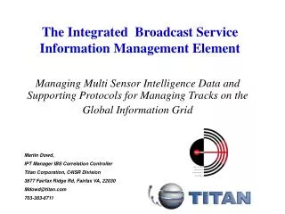
Bridging & Broadcast Scenarios
110 likes | 233 Vues
This paper explores the complexities of managing access network topologies in telecom environments, focusing on the Single Copy Broadcast (SCB) mechanism while ensuring compliance with the Spanning Tree Protocol (STP). It discusses the critical need for service providers to maintain control over network topology, addresses potential conflicts in P2P emulation modes, and presents case studies illustrating SCB performance. The necessity for standardized VLAN implementations and strategies to prevent broadcast floods and routing issues is emphasized, paving the way for enhanced multimedia application support and bandwidth efficiency.

Bridging & Broadcast Scenarios
E N D
Presentation Transcript
Bridging & Broadcast Scenarios Carlos RibeiroCTBC Telecom
Bridging on the Access Network • Access network topology • The Service Provider need to have full control over the access network topology • For the Spanning Tree Protocol, this means that the SP must always be the root of the spanning tree topology • Nightmare scenarios • Multiple EFM-based SP connected together • Multihomed EFM accesses • Who is in charge of the resulting network?
Single Copy Broadcast • Desired behavior • Allows for very efficient use of bandwidth • Well suited for multimedia applications • Digital video distribution • Digital audio distribution • Conflicts with P2P emulation mode • Broadcast frames need to be copied for every user! • Potential issues • Spanning Tree Topology, broadcast floods
Case studies • Objectives • Show how do some proposed topologies behave with regards to single copy broadcast • Assumptions • EPON works in P2P emulation mode • Single Copy Broadcast is enabled • A single frame is sent to all stations downstream • No special ‘routing’ behavior for SCB • SCB is always on the downstream; upstream traffic is always subject to P2P emulation rules • If a P2P emulation port is disabled by the STP protocol, then it will discard all broadcast frames received
Single Copy Broadcast frame scb User Frame uf Single Copy Broadcast(without spanning tree) Time diagram: frame duplication due to a loop OLT Both framesare accepted DS scb Access Network scb 1 scb 2 US1 scb US2 scb ONU 1 ONU 2 1 • Configuration: • All ports work on P2P emulation mode • Downstream is seen by all ports, even with P2P emulation • It won’t work without spanning tree 2 User managed link
Single Copy Broadcast frame scb User Frame uf Single Copy Broadcast(with spanning tree: case 1) Time diagram: STP enabled, user link disabled OLT Unicast frame is received by ONU2 DS scb uf12 Access Network 1 Both framesare accepted 2 US1 uf12 US2 ONU 1 ONU 2 1 • Configuration: • The user port is disabled by the STP • Both P2P emulation ports are enabled • The user loses the internal link • Some user traffic may go through the SP network, instead of the direct route! 2 User managed link
Single Copy Broadcast frame scb User Frame uf Single Copy Broadcast(with spanning tree: case 2) Time diagram: STP enabled, one P2PE link disabled OLT ONU 2 discards the frame (link is disabled) DS scb OLT receives the frame through ONU1 Access Network scb 1 uf2O 2 US1 uf2O US2 ONU 1 ONU 2 1 • Configuration: • One P2P emulation port is disabled • The user link is still alive • Consequence: • Upstream traffic from the user network goes to the other ONU to be forwarded upstream 2 User managed link
Summary • Routing behavior is not absolutely needed • P2P Emulation can work with SCB • With STP enabled, loops are avoided, but... • User traffic may flood through the SP network • SP traffic may turn out to be carried through user links • There are no guarantees that the root will always be the SP • There may be two SP providers connected through a single customer!
Additional ideas • Force VLANs in the access network • All ports should apply SP-specific VLAN tags • All frames which enter the access network with VLAN tags applied should be tunneled with ‘VLAN-inside-VLAN’, or 802.1q inside 802.1q • This implementation resembles a ‘administrative domain’ paradigm, as already implemented for routed networks • Comment: to require 802.1q implementation may be beyond 802.3ah scope; but so is the requirement to use a router for SE support. • Special MAC addresses • Reserve MAC addresses for the applications that use single copy broadcast on the downstream • Apply filtering to avoid loops on the network
VLANs inside VLANs Service layerBridges, Routers... OLT/Bridge(802.1d compliant) S1 ONU S2 ONU S1 S3 S2 ONU S4 STP DomainInside the Access Network S1 S2 S3
VLANs inside VLANsSP Requirements • A standard way to implement VLAN-inside-VLAN • Encapsulation levels: • 1 level of encapsulation only • ‘n’ levels of encapsulation • Arbitrary encapsulation • Maximum frame size (depends on the maximum encapsulation allowed) • A standard way to provision and manage VLANs • Standard MIBs • Standard VLAN-to-VLAN mapping features