Comprehensive Guide on Tail Boom Design and Structural Weight Analysis for Aircraft
This document outlines critical design aspects of aircraft tail booms, including sizing requirements for maximum loading conditions and deflection criteria essential for maintaining structural integrity. Topics include the analysis of parts such as the fuselage, wing attachment, and landing gear, as well as considerations for pod support structures. Specific material properties, moment of inertia, and stress requirements are detailed, providing engineers with the necessary framework for designing lightweight, efficient tail support systems that ensure safety and performance.

Comprehensive Guide on Tail Boom Design and Structural Weight Analysis for Aircraft
E N D
Presentation Transcript
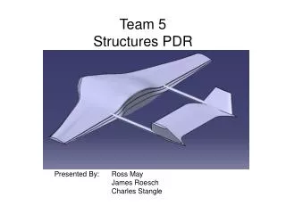
Team 5 Structures and Weights PDR #2 • Scott Bird • Mike Downes • Kelby Haase • Grant Hile • Cyrus Sigari • Sarah Umberger • Jen Watson PDR
Preview • Tail Beam Sizing • Pod Support • Wing And Landing Gear Attachment • Fuselage Layout • Parts List and Weight PDR
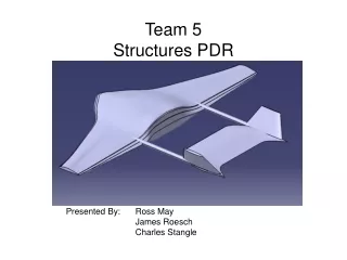
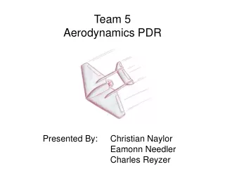
Walk-around Data Boom Robust Wing Tractor Engine Detachable Pod Simple Fuselage Design PDR
Lrdr Lel Lrdr Lel Boom Sizing • Tail boom sizing requirements: • support the maximum loading conditions • Maximum elevator and rudder deflections • Small angle of twist • Small deflection • Assumptions and Chooses • 5g (5 times gravity) is maximum lift loading • Boom support is fixed to fuselage • Spruce PDR
Maximum Loading • Maximum Lift of Rudder and Elevator • Maximum Velocity • Maximum Coefficient of Lift • Maximum deflection • Maximum Bending Moment • Longest Moment arm • Max bending at fixed end Lift x PDR
Tail Boom Property Requirements • Requirement: • My = maximum bending moment • z=distance from centroid to farthest edge • σxx = ultimate yielding stress (material property) • Iy= Moment of Inertia of cross section • Requirement: θ small degree at tip in Appendix • Requirement: is small • E=Young’s Modulus (material property) • I=depends on cross section P L PDR
Stress Criteria PDR
Twist Criteria PDR
Tip Deflection PDR
y t c h x d h c t Tail Boom Cross Section Properties • Compare Cross-Sections to Minimize Weight • Two Rectangles • Box Beam • Circular PDR
Pod Support • Considerations • Light Weight • Support Payload • Easily Removable • Two Supports • Aluminum Rods • Removable • Spacers • Brackets to hold Pod in place • Results=2.2lbs each • Too heavy? Spacer PDR hf
Wing Attachment • Desirables • Easy to remove • Support the wing • Elastic Bands • Easy to apply and remove • Spruce Rods • Solid Skin between Attachments Wing Attachments PDR
Landing Gear Attachment • Failure without disaster • Vertical • Buckle resistant • Horizontal • Fail before vertical in joint • Desired result • If Horizontal at fails joints first not much structural damage Vertical Horizontal PDR
Fuselage Layout • Considerations • Support all components • Engine • Electronics • Pod • Wing • Landing Gear • Tail • Simple • Easy to build • Aerodynamic • Smooth transitions • Foam • Composite Skins • Ribs for shape PDR
Part’s List • Yellow- Estimated • Blue -Program Estimated • Fuselage Weight not complete PDR
Finishing Touches…. • Analysis booms support of fuselage • Pod brackets, Spacers, and Bolts • Add Solid Skin to Wing • Ailerons Attachment • Engine and other Support • Finalize Weight • Update when other values changes PDR
Questions? • Questions?? PDR
Material Properties ”Selection and use of Engineering Materials”, J.A. Charles PDR
Wing Box Properties (Rotation Requirements) • Requirement: θ<1 degree at tip • T=Lift*(distance to shear center) • L=Half span • dis=distance between spars tf hf hr tr b PDR