Layer Pattern for Distributed System Architecture
Learn how to structure complex distributed systems using the Layer Pattern to separate concerns between tiers and enhance system scalability and maintainability.

Layer Pattern for Distributed System Architecture
E N D
Presentation Transcript
Some Patterns for Building Complex Distributed Systems Lodewijk Bergmans [bergmans@cs.utwente.nl] kamer 5098, tel. 4271 (using slides by Douglas Schmidt & Mehmet Aksit)
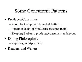
intro • practicum • patterns • oefeningen
Modalities e.g., MRI, CT, CR, Ultrasound, etc. Example: Electronic Medical Imaging Systems • Goal • Route, manage, & manipulate electronic medical images robustly, efficiently, & securely thoughout a distributed environment • System Characteristics • Large volume of “blob” data • e.g.,10 to 40 Mps • “Lossy” compression isn’t viable due to liability concerns • Diverse QoS requirements, e.g., • Synchronous & asynchronous communication • Streaming communication • Prioritization of requests & streams • Distributed resource management
Layer Pattern an architectural pattern for structuring systems [POSA, p. 31-]
Presentation Tier • e.g., thin clients Client Client Application comp • Middle Tier • e.g., business objects comp Server DB Server DB Server • Database Tier • e.g., persistent data Separating Concerns Between Tiers • Context • Distributed systems are now common due to the advent of • The global Internet • Ubiquitous mobile & embedded devices • Problem • One reason it’s hard to build COTS-based distributed systems is because a large number of capabilities must be provided to meet end-to-end application requirements • Solution • Apply the Layers architectural pattern to create a multi-tier architecture that separates concerns between groups of subtasks occurring at distinct layers in the distributed system • Services in the middle-tier participate in various types of tasks, e.g., • Workflow of integrated “business” processes • Connect to databases & other backend systems for data storage & access
Presentation Tier • e.g., radiology clients Diagnostic Workstations Clinical Workstations • Middle Tier • e.g., image routing & image transfer logic Image comp • Database Tier • e.g., persistent image data comp Image Database Image Database Server Applying the Layers Pattern to Image Acquisition • Diagnostic & clinical workstations are presentation tier components that: • Typically represent sophisticated GUI elements • Share the same address space with their clients • Their clients are containers that provide all the resources • Exchange messages with the middle tier components • Image servers are middle tier components that: • Provide server-side functionality • e.g., they are responsible for scalable concurrency & networking • Can run in their own address space • Are integrated into containers that hide low-level system details
Problem Description A large system, which is characterized with a mix of low and high level issues, where high-level operations rely on low-level issues: High-level High-level A complex system Low-level Low-level
Problem Description (cont’ed) • The mapping of high-level issues to low-level issues is not straight-forward. High-level ? High-level A complex system ? Low-level Low-level
A complex system A complex system Problem Description (cont’ed) • Portability is required;
A complex system Problem Description (cont’ed) • Several external boundaries of the system are specified a priori;
Forces to be balanced • Late code changes should not ripple through the system; • Interfaces must be stable(must be standardized if possible); • Part of the system must be exchangeable; • Future high-level extensions; conflicts
Forces to be balanced (cont’ed) • Similar responsibilities must be grouped together; • The system will be built by a team of programmers; • Performance of the system; • There is no standard component granularity; • Future high-level extensions; conflicts
Solution • Structure your system into an appropriate number of layers and place them on top of each other; • There are noother direct dependencies! Layer JProvides services used by J+1 Delegates subtasks to J-1 Layer J-1Provides services used by J Delegates subtasks to J-2
Design (implementation) 1. Define the abstraction criterion for grouping tasks; Problem? Criterion? L4L3L2L1 2. Determine the number of abstraction levels; 3. Name and assign tasks to the layers; dependencies play an important role! 4. Specify the services......and refine!
r2 L4L3L2L1 r1 Y r3 Z X Design (cont’ed) 5. Specify an interface for each layer; L4L3L2L1 6. Structure each individual layer; 7. Decouple adjacent layers;
n+2 dependency n+1 n n-1 Design: transparent layering • Dependent transparency:A layer depends on its sub-layer but is not aware of it;
depends on interprets interpreter Design: transparent layering using interpreter
Pros & Cons of the Layers Pattern • This pattern has four benefits: • Reuse of layers • If an individual layer embodies a well-defined abstraction & has a well-defined & documented interface, the layer can be reused in multiple contexts • Support for standardization • Clearly-defined and commonly-accepted levels of abstraction enable the development of standardized tasks & interfaces • Dependencies are localized • Standardized interfaces between layers usually confine the effect of code changes to the layer that is changed • Exchangeability • Individual layer implementations can be replaced by semantically-equivalent implementations without undue effort • This pattern also has liabilities: • Cascades of changing behavior • If layer interfaces & semantics aren’t abstracted properly then changes can ripple when behavior of a layer is modified • Lower efficiency • A layered architecture can be less efficient than a monolithic architecture • Unnecessary work • If some services performed by lower layers perform excessive or duplicate work not actually required by the higher layer, performance can suffer • Difficulty of establishing the correct granularity of layers • It’s important to avoid too many & too few layers
Proxy Pattern a design pattern for access control [POSA, p.263-]
Client AbstractService Proxy Service service service service pre-processing: marshaling post-processing: unmarshaling 1 1 : Client : Proxy : Service service service Improving Type-safety & Performance • Problems • Low-level message passing is fraught with accidental complexity • Remote components should look like local components from an application perspective • i.e., clients & servers should be oblivious to communication issues • Context • The configuration of components in distributed systems is often subject to change as requirements evolve Solution Apply the Proxy design pattern to provide an OO surrogate through which clients can access remote objects • AService implements the object, which is not accessible directly • A Proxy represents the Service and ensures the correct access to it • Proxy offers same interface as Service • Clients use the Proxy to access the Service
Client AbstractService Proxy Image Xfer Invoke get_image() call get_image() get_image() get_image() Image Xfer Service Xfer Proxy Radiology Client Image Database 1 1 Applying the Proxy Pattern to Image Acquisition We can apply the Proxy pattern to provide a strongly-typed interface to initiate & coordinate the downloading of images from an image database • When proxies are generated automatically by middleware they can be optimized to be much more efficient than manual message passing (Cf. CORBA) • e.g., improved memory management, data copying, & compiled marshaling/demarshaling
Pros & Cons of the Proxy Pattern • This pattern provides three benefits: • Decoupling clients from the location of server components • By putting all location information & addressing functionality into a proxy clients are not affected by migration of servers or changes in the networking infrastructure • Potential for time & space optimizations • Proxy implementations can be loaded “on-demand” and can also be used to cache values to avoid remote calls • Proxies can also be optimized to improve both type-safety & performance • Separation of housekeeping & functionality • A proxy relieves clients from burdens that do not inherently belong to the task the client performs • This pattern has two liabilities: • Potential overkill via sophisticated strategies • If proxies include overly sophisticated functionality they many introduce overhead that defeats their intended purpose • Less efficiency due to indirection • Proxies introduce an additional layer of indirection that can be excessive if the proxy implementation is inefficient
Broker Pattern an architectural pattern for distributed systems [POSA, p.99-]
Broker 1 1 Server Proxy Client Proxy * * message exchange main_loop srv_registration srv_lookup transmit_message message exchange marshal unmarshal dispatch receive_request marshal unmarhal receive_result service_p 1 calls * calls * calls 1 Bridge 1 Server marshal unmarshal forward_message transmit_message Client start_up main_loop service_i call_service_p start_task Ensuring Platform-neutral & Network-transparent OO Communication • Context • Using the Proxy pattern is insufficient since it doesn‘t address how • Remote components are located • Connections are established • Messages are exchanged across a network • etc. Problem • We need an architecture that: • Supports remote method invocation • Provides location transparency • Allows the addition, exchange, or remove of services dynamically • Hides system details from the developer • Solution • Apply the Broker pattern to provide OO platform-neutral communication between networked client & server components
Interface Specif. Proxy Code Generator Broker Pattern Dynamics : Client : Server : ServerProxy : Client Proxy : Broker register_service start_up method (proxy) assigned port locate_server server port marshal receive_request unmarshal dispatch method (impl.) result marshal receive_result unmarshal result Broker tools provide the generation of necessary client & server proxies from higher level interface definitions
This pattern has five benefits: Portability enhancements A broker hides OS & network system details from clients and servers by using indirection layers, such as APIs, proxies, adapters, & bridges Interoperability with other brokers Different brokers may interoperate if they understand a common protocol for exchanging messages Reusability of services When building new applications, brokers enable application functionality to reuse existing services Location transparency A broker is responsible for locating servers, so clients need not know where servers are located Changeability & extensibility of components If server implementations change without affecting interfaces clients should not be affected This pattern also has liabilities: Restricted efficiency Applications using brokers may be slower than applications written manually Lower fault tolerance Compared with non-distributed software applications, distributed broker systems may incur lower fault tolerance Testing & debugging may be harder Testing & debugging of distributed systems is tedious because of all the components involved Pros & Cons of the Broker Pattern
Publisher-Subscriber Pattern(Observer) a design pattern for communication [POSA, p. 339-]
Subscriber Filter consume filter Event Publisher Event Channel attachPublisher detachPublisher attachSubscriber detachSubscriber produce creates receives * Decoupling Suppliers & Consumers • Context • In large-scale electronic medical imaging systems, radiologists may share “work lists” of patient images to balance workloads effectively • Problem • Having each client call a specific server is inefficient & non-scalable • A polling strategy leads to performance bottlenecks • Work lists could be spread across different servers • More than one client may be interested in work list content • Solution • Apply the Publisher/Subscriber pattern to decouple image suppliers from image consumers • Decouple suppliers (publishers) & consumers (subscribers) of events: • An Event Channel stores events • Publishers create events & store them in a queue maintained by the Event Channel • Consumers register with event queues, from which they retrieve events • Events are used to transmit state change info from publishers to consumers • For event transmission push-models & pull-models are possible • Filters can filter events for consumers
: Publisher : Event Channel : Subscriber attachSubscriber : Event pushEvent event pushEvent produce event consume detachSubscriber Publisher/Subscriber Pattern Dynamics • The Publisher/Subscriber pattern helps keep the state of cooperating components synchronized • To achieve this it enables one-way propagation of changes: one publisher notifies any number of subscribers about changes to its state • Key design considerations for the Publisher/Subscriber pattern include: • Push vs. pull interaction models • Control vs. data event notification models • Multicast vs. unicast communication models • Persistence vs. transcient queueing models
Event Channel Filter Modality Radiologist attachPublisher detachPublisher attachSubscriber detachSubscriber produce filter consume Event creates receives * Radiology Client Radiology Client Radiology Client Event Channel Radiology Client Radiology Client Image Database Applying the Publisher/Subscriber Pattern to Image Acquisition • Radiologists can subscribe to an event channel in order to receive notifications when modalities publish events indicating the arrival of a new image • This design enables a group of distributed radiologists to collaborate effectively in a networked environment
Pros & Cons of the Publisher/Subscriber Pattern • This pattern has two benefits: • Decouples consumers & producers of events • All an event channel knows is that it has a list of consumers, each conforming to the simple interface of the Subscriber class • Thus, the coupling between the publishers and subscribers is abstract & minimal • n:m communication models are supported • Unlike an ordinary request/response interaction, the notification that a publisher sends needn’t designate its receiver, which enables a broader range of communication topologies, including multicast & broadcast • There are also a liability: • Must be careful with potential update cascades • Since subscribers have no knowledge of each other’s presence, applications can be blind to the ultimate cost of publishing events through an event channel • Thus, a seemingly innocuous operation on the subject may cause a cascade of updates to observers & their dependent objects
Summary • Layers architectural pattern • helps to structure applications that can be decomposed into groups of subtasks in which each group of subtasks is at a particular level of abstraction • Proxy Design pattern • makes the clients of a component communicate with a representative rather than to the component itself
Summary-2 • Broker architectural pattern • can be used to structure distributed software systems with decoupled components that interact by remote service invocations • a broker component is responsible for coordinating communication • Publisher-Subscriber design pattern • helps to keep the state of cooperating components synchronized. To achieve this it enables one-way propagatioin of changes: one publisher notifies any number of subscribers
Overview of Distributed Object Computing Communication Mechanisms Context In multi-tier systems both the tiers & the components within the tiers must be connected via communication mechanisms • Problem • A single communication mechanism does not fit all uses! Solution • DOC middleware provides multiple types of communication mechanisms • Collocated client/server (i.e., native function call) • Synchronous & asynchronous RPC/IPC • Group communication • Data streaming Next, we’ll explore various patterns that applications can apply to leverage these communication mechanisms
7.New Naming Service 3. Bind Factory 13. Activate 4. Find Factory 14. Delegate Container 8. New 5. Find Image 10. Invoke get_image() call 2. Enter info 9. Return Ref 11. Query Config. 1. Deploy Configuration Configuration Database 6. Intercept & delegate 12. Check Authorization Security Service Factory/Finder Image Acquisition Scenario Diagnostic & Clinical Workstations Image Xfer Interface Image Xfer Component Servant Factory Proxy Radiology Client Image Database Xfer Proxy • Key Tasks • Image routing • Image delivery
Applying Patterns to Resolve Key Design Challenges Image Xfer Interface Component Configurator Naming Service Proxy Layers Extension Interface Image Xfer Component Servant Container Active Object Factory Proxy Radiology Client Publisher/ Subscriber Image Database Xfer Proxy Activator Configuration Database Configuration Broker Interceptor Async Forwarder/ Receiver Security Service Factory/Finder Factory/Finder Patterns help resolve the following common design challenges: • Separating concerns between tiers • Improving type-safety & performance • Enabling client extensibility • Ensuring platform-neutral & network-transparent OO comm. • Supporting async comm. • Supporting OO async comm. • Decoupling suppliers & consumers • Providing mechanisms to find & create remote components • Locating & creating components effectively • Extending components transparently • Minimizing resource utilization • Enhancing server (re)configurability
Applying the Broker Pattern to Image Acquisition • Common Object Request Broker Architecture (CORBA) • CORBA defines interfaces • Rather than implementations • Simplifies development of distributed applications by automating • Object location • Connection management • Memory management • Parameter (de)marshaling • Event & request demuxing • Error handling • Object/server activation • Concurrency • CORBA shields applications from environment heterogeneity • e.g., programming languages, operating systems, networking protocols, hardware