Lecture 21 – Splices and Shear
610 likes | 964 Vues
Lecture 21 – Splices and Shear. February 5, 2003 CVEN 444. Lecture Goals. Spice Shear Shear Design. Why do we need bar splices? -- for long spans Types of Splices 1. Butted &Welded 2. Mechanical Connectors 3. Lay Splices. Must develop 125% of yield strength. Bar Splices.

Lecture 21 – Splices and Shear
E N D
Presentation Transcript
Lecture 21 – Splices and Shear February 5, 2003 CVEN 444
Lecture Goals • Spice • Shear • Shear Design
Why do we need bar splices? -- for long spans Types of Splices 1. Butted &Welded 2. Mechanical Connectors 3. Lay Splices Must develop 125% of yield strength Bar Splices
Why do we need bar splices? -- for long spans Types of Splices 1. Contact Splice 2. Non Contact Spice (distance 6” and 1/5 splice length) Splice length is the distance the two bars are overlapped. Tension Lap Splices
Class A Spice (ACI 12.15.2) When over entire splice length. and 1/2 or less of total reinforcement is spliced win the req’d lay length. Types of Splices
Types of Splices Class B Spice (ACI 12.15.2) All tension lay splices not meeting requirements of Class A Splices
Tension Lap Splice (ACI 12.15) where As (req’d) = determined for bending ld = development length for bars (not allowed to use excess reinforcement modification factor) ld must be greater than or equal to 12 in.
Tension Lap Splice (ACI 12.15) Lap Spices shall not be used for bars larger than No. 11. (ACI 12.14.2) Lap Spices should be placed in away from regions of high tensile stresses -locate near points of inflection (ACI 12.15.1)
Lap, req’d = 0.0005fy db for fy < 60000 psi Lap, req’d = (0.0009fy -24) db for fy > 60000 psi Lap, req’d 12 in For fc 3000 psi, required lap splice shall be multiply by (4/3) (ACI 12.16.1) Compression Lap Splice (ACI 12.16.1)
In tied column splices with effective tie area throughout splice length 0.0015 hs factor = 0.83 In spiral column splices, factor = 0.75 But final splice length 12 in. Compression Lap Splice (ACI 12.17)
Calculate the lap-splice length for 6 #8 tension bottom bars in two rows with clear spacing 2.5 in. and a clear cover, 1.5 in., for the following cases a. b. c. When 3 bars are spliced and As(provided) /As(required) >2 When 4 bars are spliced and As(provided) /As(required) < 2 When all bars are spliced at the same location. fc= 5 ksi and fy = 60 ksi Example – Splice Tension
Example – Splice Tension For #8 bars, db =1.0 in. and a = ?b =? g = ?l =?
Example – Splice Tension The As(provided) /As(required) > 2, class ? splice applies; The As(provided) /As(required) < 2, class ? splice applies;
Example – Splice Compression Calculate the lap splice length for a # 10 compression bar in tied column when fc= 5 ksi and when a) fy = 60 ksi and b) fy = 80 ksi
Example – Splice Compression For #10 bars, db =? in. Check ls > 0.005 db fy
Example – Splice Compression For #10 bars, db =? in. The ld = 2? in. Check ls > (0.0009 fy –24) db So use ls = ? in.
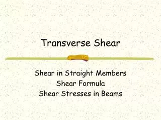
Uncracked Elastic Beam Behavior Look at the shear and bending moment diagrams. The acting shear stress distribution on the beam.
Uncracked Elastic Beam Behavior The acting stresses distributed across the cross-section. The shear stress acting on the rectangular beam.
Uncracked Elastic Beam Behavior The equation of the shear stress for a rectangular beam is given as: Note: The maximum 1st moment occurs at the neutral axis (NA).
Uncracked Elastic Beam Behavior The ideal shear stress distribution can be described as:
Uncracked Elastic Beam Behavior A realistic description of the shear distribution is shown as:
Uncracked Elastic Beam Behavior The shear stress acting along the beam can be described with a stress block: Using Mohr’s circle, the stress block can be manipulated to find the maximum shear and the crack formation.
Inclined Cracking in Reinforced Concrete Beams Typical Crack Patterns for a deep beam
Inclined Cracking in Reinforced Concrete Beams Flexural-shear crack - Starts out as a flexural crack and propagates due to shear stress. Flexural cracks in beams are vertical (perpendicular to the tension face).
Inclined Cracking in Reinforced Concrete Beams For deep beam the cracks are given as: The shear cracks Inclined (diagonal) intercept crack with longitudinal bars plus vertical or inclined reinforcement.
Inclined Cracking in Reinforced Concrete Beams For deep beam the cracks are given as: The shear cracks fail due two modes: - shear-tension failure - shear-compression failure
Shear Strength of RC Beams without Web Reinforcement Total Resistance = vcz + vay + vd (when no stirrups are used) vcz - shear in compression zone va - Aggregate Interlock forces vd = Dowel action from longitudinal bars Note: vcz increases from (V/bd) to (V/by) as crack forms.
(1) Tensile Strength of concrete affect inclined cracking load Strength of Concrete in Shear (No Shear Reinforcement)
(2) Longitudinal Reinforcement Ratio, rw Strength of Concrete in Shear (No Shear Reinforcement)
Strength of Concrete in Shear (No Shear Reinforcement) (3) Shear span to depth ratio, a/d (M/(Vd)) Deep shear spans more detail design required Ratio has little effect
(4) Size of Beam Increase Depth Reduced shear stress at inclined cracking Strength of Concrete in Shear (No Shear Reinforcement)
(5) Axial Forces - Axial tension Decreases inclined cracking load - Axial Compression Increases inclined cracking load (Delays flexural cracking) Strength of Concrete in Shear (No Shear Reinforcement)
Function: Web Reinforcement is provided to ensure that the full flexural capacity can be developed. (desired a flexural failure mode - shear failure is brittle) - Acts as “clamps” to keep shear cracks from widening Function and Strength of Web Reinforcement
Function and Strength of Web Reinforcement • Uncracked Beam Shear is resisted uncracked concrete. • Flexural Cracking Shear is resisted by vcz, vay,vd
Function and Strength of Web Reinforcement • Flexural Cracking Shear is resisted by vcz, vay, vd and vs Vs increases as cracks widen until yielding of stirrups then stirrups provide constant resistance.
Designing to Resist Shear Shear Strength (ACI 318 Sec 11.1)
Designing to Resist Shear Shear Strength (ACI 318 Sec 11.1) Nominal shear resistance provided by concrete Nominal shear provided by the shear reinforcement
Shear Strength Provided by Concrete Bending only Simple formula More detailed Note: Eqn [11.3] Eqn [11.5]
Bending and Axial Compression Simple formula Nu is positive for compression and Nu/Ag are in psi. Eqn [11.4] Eqn [11.7] Shear Strength Provided by Concrete
Typical Shear Reinforcement Stirrup - perpendicular to axis of members (minimum labor - more material) ACI Eqn 11-15
Typical Shear Reinforcement Bent Bars (more labor - minimum material) see req’d in 11.5.6 ACI 11-5.6
Stirrup Anchorage Requirements Vs based on assumption stirrups yield Stirrups must be well anchored.
Stirrup Anchorage Requirements Refer to Sec. 12.13 of ACI 318 for development of web reinforcement. Requirements: • each bend must enclose a long bar • # 5 and smaller can use standard hooks 90o,135o, 180o • #6, #7,#8( fy = 40 ksi ) • #6, #7,#8 ( fy > 40 ksi ) standard hook plus a minimum embedment
Stirrup Anchorage Requirements Also sec. 7.10 requirement for minimum stirrups in beams with compression reinforcement, beams subject to stress reversals, or beams subject to torsion
Design Procedure for Shear (1) Calculate Vu (2) Calculate fVc Eqn 11-3 or 11-5 (no axial force) (3) Check If yes, add web reinforcement (go to 4) If no, done.
Design Procedure for Shear Provide minimum shear reinforcement (4) Also: (Done)
Design Procedure for Shear (5) Check:
Design Procedure for Shear (6) Solve for required stirrup spacing(strength) Assume # 3, #4, or #5 stirrups from 11-15
Design Procedure for Shear (7) Check minimum steel requirement (eqn 11-13)