Download
1 / 24
240 likes | 347 Vues
Dive into the world of electrical filters with this comprehensive guide. Learn about various filter types, such as low-pass, high-pass, and band-pass, their applications, and how to create your own filters using circuit elements. Understand essential concepts like the -3dB point, gain measurements, frequency response graphs, and cutoff frequencies. Engage in practical tasks like building a crystal set radio and identifying filters based on generated graphs. Enhance your understanding of electrical terminology and circuit components, including resistors, capacitors, and inductors. Get ready to conduct experiments, analyze data, prepare reports, and deliver professional presentations. Experiment, learn, and explore the fascinating realm of electronic filters!

E N D
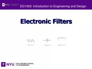
EG1003: Introduction to Engineering and Design Electronic Filters
Overview • Objectives • Background • Materials • Procedure • Report / Presentation • Closing
Objectives • Learn about electrical filters • Different types • Uses • What is the -3dB point? • Create filters and a crystal set radio using multiple circuit elements • Identify filters based on generated graphs
Frequency Response Graph • Gain (in dB) • Ratio of output against input • 20*log (Vout/Vin) • Always negative value • -3dB Point • 3dB drop of signal power from highest point on gain • Signal power is half of original value • Cutoff Frequency (in Hz) • Frequency at -3dB Point
Max Gain (dB) Gain (dB) (linear scale) Gain is 3 dB lower than the max 3 dB Bandwidth f (kHz) (log scale) Cutoff Frequency Gain vs. Frequency Frequency Response Graph • Plot of Gain versus Frequency of electrical signal • Semi-logarithmic scale • Linear Y-axis, logarithmic X-axis
What are Filters? • Eliminate unwanted frequencies • High-pass or low-pass • Favor desired frequencies • Band-pass • Bandwidth: frequency range filter allows to pass • Example • Radio tunes in to particular station
Basic Filter Types • Low-Pass Filter • Low frequencies pass • Low-Pass • High-Pass • Band-Pass IGNORE 3dB Point:-3dB Cutoff Frequency: 1590 Hz Bandwidth:0 - 1590 Hz PASS
Basic Filter Types • High-Pass Filter • High frequencies pass • Low-Pass • High-Pass • Band-Pass IGNORE 3dB Point: -3dB Cutoff Frequency: 160 Hz Bandwidth:160 - ∞ Hz PASS
Basic Filter Types • Band-Pass Filter • Limited frequency range passes • Low-Pass • High-Pass • Band-Pass IGNORE IGNORE 3dB Point: -3dB Cutoff Frequencies: 400 and 600 Hz Bandwidth:400 - 600 Hz Resonant Frequency (High Response Point): 500 Hz PASS
Electrical Terminology • Voltage (V) [unit = V for Volts] • Potential difference in electrical energy • Current (I) [unit = A for Amperes] • Charge flow rate • Can be positive or negative • Terms • Elements • Wiring
Symbol Electrical Terminology • Resistor (R) [unit = Ω for Ohms] • Resists flow of electrical current • Dissipates electrical energy as heat • Often used to alter voltages in circuits • Characterized by Ohm’s Law: V = I*R • Not sensitive to frequency • Uses a poor conductor • Example: Carbon • Terms • Elements • Wiring
Symbol Electrical Terminology • Capacitor (C)[unit = F for Farads] • Stores potential energy (V) • Affected by voltage and frequency • A pair metal plates separated by non-conductive material • Example: Air • Electrical charge accumulates on plates • Terms • Elements • Wiring
Symbol Electrical Terminology • Inductor (L)[unit = H for Henries] • Stores and delivers energy in a magnetic field • Magnetic fields affect the current of a circuit • Effected by current and frequency • Is a coil of wire • Terms • Elements • Wiring
Electrical Terminology • Series • Same current through all elements • Vin = VA + VB + VC • Parallel • Same voltage across all branches • Vin = VD = VE = VF + VG • Terms • Elements • Wiring
Materials for Lab • Resistors • Brown, black, yellow = 100KΩ • Brown, black, green = 1MΩ • Capacitors • 102 = 0.001 µF • 10J = 10pF • Inductors • 1mH
Materials for Lab (Cont’d) • NI-ELVIS II+ • Breadboard • Coaxial to Alligator Clip Cable
Procedure - Testing • Plug in NI ELVIS II to PC Lab and turn it on • Select NI ELVISmx Instrument Launcher • Select FGEN in the Instrument Launcher • Set function generator to 1000Hz • Set the amplitude to 2 Vpp • Set signal route to FGEN BNC • Select Scope in the Instrument Launcher
Procedure – Data Analysis • Click run in both instruments • Calculate the -3dB point • Test both of the circuits and determine their type • Assemble the radio
Procedure - Circuit 1 • Connect the 100kΩ resistor and .001 µF capacitor in series
Connect 0.001 µF capacitor to 1 MΩ resistor in series Procedure - Circuit 2
Procedure - Circuit 3 • Assemble the circuit below (Crystal Radio)
Assignment: Report • Individual Report (one report per student) • Title page • Discussion topics in the manual • For all circuits • Include Excel tables and Gain vs. Frequency graphs • Determine filter type • Label each graph with determined filter type • OPTIONAL- Include photos of circuits and setup
Assignment: Presentation • Team Presentation • Include lab data • Professional-looking tables • Discussion topics in the manual • Include photos of circuits and setup • Refer to “Creating PowerPoint Presentations” found in Online Manual
Closing • TA will assign which circuit you start with • Have all original data signed by your TA • All team members must actively participate in experiment • Submit all work electronically • Return all materials to your TA