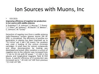
ION SOURCES FOR MEIC
ION SOURCES FOR MEIC. Vadim Dudnikov Muons, Inc., Batavia, IL. Mini-Workshop for MEIC Ion Complex Design, Jefferson Lab. Jan 27, 2011. Abstract.

ION SOURCES FOR MEIC
E N D
Presentation Transcript
ION SOURCES FOR MEIC Vadim Dudnikov Muons, Inc., Batavia, IL Mini-Workshop for MEIC Ion Complex Design, Jefferson Lab. Jan 27, 2011
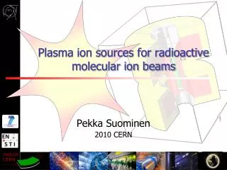
Abstract • Ion sources for production of polarized negative and positive light and heavy ions will be considered. Universal Atomic bean ion source can be used for generation of polarized H-, H+, D-, D+ , He++, Li +++ ions with high polarization and high brightness. • Generation of multicharged ions, injection and beam instabilities will be considered. References: • Belov A.S., Dudnikov V.,et. al., NIM A255, 442 (1987). • Belov A.S., Dudnikov V.,et al., . NIM A333, 256 (1993). • Belov A.S, Dudnikov V., et. al., RSI, 67, 1293 (1996). • Bel’chenko Yu. I. , Dudnikov V., et. al., RSI, 61, 378 (1990) • Belov A.S. et. al., NIM, A239, 443 (1985). • Belov A.S. et. al., 11 th International Conference on Ion Sources, Caen, France, • September 12-16, 2005; • A.S. Belov, PSTP-2007, BNL, USA; A.S. Belov, DSPIN2009, DUBNA, Russia; • A. Zelenski,PSTP-2007, BNL, USA; DSPIN2009, DUBNA, Russia
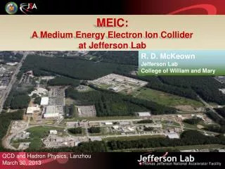
EIC Design Goals • Energy • Center-of-mass energy between 20 GeV and 90 GeV • energy asymmetry of ~ 10, 3 GeV electron on 30 GeV proton/15 GeV/n ion up to 9 GeV electron on 225 GeV proton/100 GeV/n ion • Luminosity • 1033 up to 1035 cm-2 s-1per interaction point • Ion Species • Polarized H, D, 3He, possibly Li • Up to heavy ion A = 208, all striped • Polarization • Longitudinal polarization at the IP for both beams • Transverse polarization of ions • Spin-flip of both beams • All polarizations >70% desirable • Positron Beamdesirable Yuhong Zhang For the ELIC Study Group Jefferson Lab
ELIC Design Goals Energy Wide CM energy range between 10 GeV and 100 GeV Low energy: 3 to 10 GeV e on 3 to 12 GeV/c p (and ion) Medium energy: up to 11 GeV e on 60 GeV p or 30 GeV/n ion and for future upgrade High energy: up to 10 GeV e on 250 GeV p or 100 GeV/n ion Luminosity 1033 up to 1035 cm-2 s-1per collision point Multiple interaction points Ion Species Polarized H, D, 3He, possibly Li Up to heavy ion A = 208, all stripped Polarization Longitudinal at the IP for both beams, transverse of ions Spin-flip of both beams All polarizations >70% desirable Positron Beamdesirable Andrew Hutton
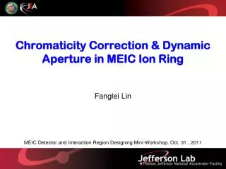
MEIC: Low and Medium Energy • Three compact rings: • 3 to 11 GeV electron • Up to 12 GeV/c proton (warm) • Up to 60 GeV/c proton (cold)
MEIC: Detailed Layout polarimetry
ELIC: High Energy & Staging p Ion Sources SRF Linac prebooster p p Serves as a large booster to the full energy collider ring MEIC collider ring ELIC collider ring e e e injector 12 GeV CEBAF electron ring Interaction Point Ion ring Vertical crossing
ELIC Main Parameters High energy Low energy Medium energy
Achieving High Luminosity MEIC design luminosity L~ 4x1034 cm-2 s-1 for medium energy (60 GeV x 3 GeV) Luminosity Concepts • High bunch collision frequency (0.5 GHz, can be up to 1.5 GHz) • Very small bunch charge (<3x10¹⁰ particles per bunch) • Very small beam spot size at collision points (β*y ~ 5 mm) • Short ion bunches (σz ~ 5 mm) Keys to implementing these concepts • Making very short ion bunches with small emittance • SRF ion linac and (staged) electron cooling • Need crab crossing for colliding beams Additional ideas/concepts • Relative long bunch (comparing to beta*) for very low ion energy • Large synchrotron tunes to suppress synchrotron-betatron resonances • Equal (fractional) phase advance between IPs
Forming a High-Intensity Ion Beam Stacking/accumulation process Multi-turn (~20) pulse injection from SRF linac into the prebooster Damping/cooling of injected beam Accumulation of 1 A coasted beam at space charge limited emittance Fill prebooster/large booster, then acceleration Switch to collider ring for booster, RF bunching & staged cooling cooling low energy ring SRF Linac Stacking proton beam in ACR source pre-booster-Accumulator ring Medium energy collider ring
Stacking polarized proton beam over space charge limit in pre-booster To minimize the space charge impact on transverse emittance, the circular painting technique can be used at stacking. Such technique was originally proposed for stacking proton beam in SNS [7]. In this concept, optics of booster ring is designed strong coupled in order to realize circular (rotating) betatron eigen modes of two opposite helicities. During injection, only one of two circular modes is filled with the injected beam. This mode grows in size (emittance) while the other mode is not changed. The beam sizes after stacking, hence, tune shifts for both modes are then determined by the radius of the filled mode. Thus, reduction of tune shift by a factor of k (at a given accumulated current) will be paid by increase of the 4D emittance by the same factor, but not k2. Stacking proton beam in pre-booster over space charge limit: 1 – painting resonators 2, 3 – beam raster resonators 4 – focusing triplet 5 – stripping foil Circular painting principle: transverse velocity of injected beam is in correlation with vortex of a circular mode at stripping foil
Overcoming space charge at stacking This reduction of the 4D emittance growth at stacking 1-3 Amps of light ions is critical for effective use of electron cooling in collider ring.
Future Accelerator R&D Focal Point 3: Forming high-intensity short-bunch ion beams & cooling sub tasks: Ion bunch dynamics and space charge effects (simulations) Electron cooling dynamics (simulations) Dynamics of cooling electron bunch in ERL circulator ring Led by Peter Ostroumov (ANL) Focal Point 4: Beam-beam interaction sub tasks: Include crab crossing and/or space charge Include multiple bunches and Interaction Points Led by Yuhong Zhang and Balsa Terzic (JLab) Additional design and R&D studies Electron spin tracking, ion source development Transfer line design
MEIC (e/A) Design Parameters * Luminosity is given per unclean per IP
High polarization importance High beam polarization is essential to the scientific productivity of a collider. Techniques such as charge-exchange injection and use of Siberian snakes allow acceleration of polarized beams to very high energies with little or no polarization loss. The final beam polarization is then determined by the source polarization. Therefore, ion sources with performances exceeding those achieved today are key requirements for the development of the next generation high-luminosity high-polarization colliders.
Existing Sources Parameters Universal Atomic Beam Polarized Sources (most promising, less expensive for repeating): • IUCF/INR CIPIOS: pulse width up to 0.5 ms; repetition 2Hz (Shutdown 8/02; Rebuilded in Dubna); Peak Intensity H-/D- 2.0 mA/2.2 mA; Max Pz/Pzz 85% to 91%; Emittance (90%) 1.2 π·mm·mrad. • INR Moscow: pulse width > 0.1 ms; repetition 5Hz (Test Bed since 1984); Peak Intensity H+/H- 11 mA/4 mA; Max Pz 80%/95%; Emittance (90)% 1.0 π·mm·mrad/ 1.8 π·mm·mrad; Unpolarized H-/D- 150/60 mA. OPPIS/BNL: H- only; Pulse Width 0.5 ms (in operation); Peak Intensity up to 1.6 mA; Max Pz 85% of nominal Emittance (90%) 2.0 π·mm·mrad.
Polarization detected • Proton polarization up to 95 % was measured with low plasma ion flux (5mA D+) • Polarization of 80% has been recorded for high ion flux in the storage cell A.S. Belov, PSTP-2007, BNL, USA
ABPIS basis • Polarized ions are produced in polarized ion sources via several steps process: • polarization of neutral atoms (atomic beam method or optical pumping) • Conversion of polarized neutral atoms into polarized ions (ionization byelectron impact, electron impact + charge-exchange, charge exchange, nearly resonant charge-exchange ) • Nearly resonant charge-exchange processes have large cross sections. This is base for high efficiency of polarized atoms conversion into polarized ions. A.S. Belov, PSTP-2007, BNL, USA
ABIS with Resonant Charge Exchange Ionization INR Moscow • H0↑+ D+ ⇒H+↑+ D0 • D0↑+ H+ ⇒D+↑+ H0 • σ~ 5 10-15cm2 • H0↑+ D−⇒H−↑+ D0 • D0↑+ H−⇒D−↑+ H0 • σ~ 10-14cm2 Limitations: Pumping is high; Extraction voltage Uex<25 kV. A. Belov, DSPIN2009
Atomic Beam Polarized Ion source In the ABS, hydrogen or deuterium atoms are formed by dissociation of molecular gas, typically in a RF discharge. The atomic flux is cooled to a temperature 30K - 80K by passing through a cryogenically cooled nozzle. The atoms escape from the nozzle orifice into a vacuum and are collimated to form a beam. The beam passes through a region with inhomogeneous magnetic field created by sextupole magnets where atoms with electron spin up are focused and atoms with electron spin down are defocused.Nuclear polarization of the beam is increased by inducing transitions between the spin states of the atoms. The transition units are also used for a fast reversal of nuclear spin direction without change of the atomic beam intensity and divergence. Several schemes of sextupole magnets and RF transition units are used in the hydrogen or deuterium ABS. For atomic hydrogen, a typical scheme consists of two sextupole magnets followed by weak field and strong field RF transition units. In this case, the theoretical proton polarization will reach Pz = -1. Switching between these two states is performed by switching between operation of the weak field and the strong field RF transition units. For atomic deuterium, two sextupole magnets and three RF transitions are used in order to get deuterons with vector polarization of Pz = -1 and tensor polarization of Pzz= +1, -2Different methods for ionizing polarized atoms and their conversion into negative ions were developed in many laboratories. The techniques depended on the type of accelerator where the source is used and the required characteristics of the polarized ion beam (see ref. [2] for a review of current sources).For the pulsed atomic beam-type polarized ion source (ABPIS) the most efficient method was developed at INR, Moscow [3-5]. Polarized hydrogen atoms with thermal energy are injected into a deuterium plasma where polarized protons or negative hydrogen ions are formed due to the quasi-resonant charge-exchange reaction:
Ionization of Polarized Atoms Resonant charge-exchange reaction is charge exchange between atom and ion of the same atom: A0 + A+ →A + + A0 • Cross -section is of order of 10-14 cm2 at low collision energy • Charge-exchange between polarized atoms and ions of isotope relative the polarized atoms to reduce unpolarized background • W. Haeberli proposed in 1968 an ionizer with colliding beams of ~1-2 keV D- ions and thermal polarized hydrogen atoms: H0↑+ D−⇒H−↑+ D0
Cross-section vs collision energy for process H+ H0 H0 + H =10-14 cm2 at ~10eV collision energy
Cross-section vs collision energy for process He++ + He0 He0 + He++ =510-16 cm2 at ~10eV collision energy
Destruction of Negative Hydrogen Ions in Plasma • H+ e H0 + 2e ~ 410-15 cm2 • H+ D+ H0 + D0 ~ 210-14 cm2 • H+ D0 H0 + D ~ 10-14 cm2 • H+ D2 H0 + D2+ e ~ 210-16 cm2 • H+ D0 HD0 + e ~ 10-15 cm2
Resonance Charge Exchange Ionizer with Two Steps Surface Plasma Converter Jet of plasma is guided by magnetic field to internal surface of cone; fast atoms bombard a cylindrical surface of surface plasma converter initiating a secondary emission of negative ions increased by cesium adsorption.
Schematic of Negative Ion Formation on the Surface (Φ>s)(formation of secondary ion emission; Michail Kishinevsky, Sov. Phys. Tech. Phys, 45,1975) • Affinity lever S is lowering by image forces below Fermi level during particle approaching to the surface; • Electron tunneling to the affinity level; • During particle moving out of surface electron affinity level S go up and the electron will tunneling back to the Fermi level; • Back tunneling probability w is high at slow moving (thermal) and can be low for fast moving particles; Ionization coefficient β- can be high ~0.5 for fast particles with S<~ φ
Coefficient of Negative Ionization As Function of Work Function and Particle Speed Kishinevsky M. E., Sov. Phys. Tech. Phys., 48 (1978), 773; 23 (1978), 456
Probability of H- Emission as Function of Work Function (Cesium Coverage) The surface work function decreases with deposition of particles with low ionization potential and the probability of secondary negative ion emission increases greatly from the surface bombarded by plasma particles. Dependences of work function on surface cesium concentration for different W crystalline surfaces (1-(001); 2-(110); 3-(111); 4-(112), left scale) and 5-relative yield Y of H- secondary emission for surface index (111), right scale
Production of Surfaces with Low Work Function (Cesium Coverage) The surface work function decreases with deposition of particles with low ionization potential (CS) and the probability of secondary negative ion emission increases greatly from the surface bombarded by plasma particles. Dependences of desorption energy H on surface Cesium concentration N for different W crystalline surfaces: 1-(001); 2-(110); 3-(111); 4-(112). • The work function in the case of cesium adsorption in dependence upon the ratio of sample temperature T to cesium-tank temperature TCs for collectors of • a molybdenum polycrystalline with a tungsten layer on the surface, • (110) molybdenum, • a molybdenum polycrystalline, • an LaB6 polycrystalline.
Probability of particles and energy reflection for low energy H particles
INR ABIS: Oscilloscope Track of Polarized H- ion Polarized H- ion current 4 mA (vertical scale-1mA/div) Unpolarized D- ion current 60 mA (10mA/div) A. Belov
ABIS polarized H-/D- source in Institute of Nuclear Research, Troitsk, Russia A possiblePrototype of Universal Atomic Beam Polarized ion source (H-, D-, Li-, He+, H+, D+, Li+); left- solenoid of resonant change exchange Ionizer; right- atomic beam source with RF dissociator.
Main Systems of INR ABIS with Resonant Charge Exchange Ionization
Main Systems of INR ABIS with Resonant Charge Exchange Ionization
Main Systems of INR ABIS with Resonant Charge Exchange Ionization
Schematic Diagram of IUCF APPIS with Resonant Charge Exchange Ionization
The pulsed polarized negative ion source (CIPIOS) multi-milliampere beams for injection into the Cooler Injector Synchrotron (CIS). Schematic of ion source and LEBT showing the entrance tothe RFQ. The beam is extracted from the ionizer toward the ABS and is then deflected downward with a magnetic bend and towards the RFQ with an electrostatic bend. This results in a nearly vertical polarization at the RFQ entrance. Belov, Derenchuk, PAC 2001
Plans of Work • Review of existing versions of ABPIS components for choosing an optimal combinations; • Review production of highest polarization; • General design of optimal ABPIS; • Estimation availability of components and materials; • Estimation of project cost and R&D schedule. • INR, A. Belov • BINP, D. Toporkov, V. Davydenko, • BNL, A. Zelenski, • IUCF, Dubna, V. Derenchuk, A. Belov, • COSY/Julich, R. Gebel.
Components of IUCF ABPIS (sextupole, ionization solenoid, RF dissociator, bending magnet, Arc discharge plasma source)
Arc Discharge Ion Source Dimov BINP 1962 Ionization 99.9 %, dissociation 99%, transverse ion temperature 0.2 eV; multi-slit extraction.
Long Pulse Arc-discharge Plasma Generator with Lab6 Cathode Version with one LaB6 disc Version with several LaB6 discs Metal-ceramic discharge channel is developed
1 -current feedthrough; 2- housing; 3-clamping screw; 4-coil; 5- magnet core; 6-shield; 7-screw; 8-copper insert; 9-yoke; 10-rubber washer- returning springs; 11-ferromagnetic plate- armature; 12-viton stop; 13-viton seal; 14-sealing ring; 15-aperture; 16-base; 17-nut. Fast, compact gas valve, 0.1ms, 0.8 kHz
Cesium oven with cesium pellets and press-form for pellets preparation. 37-cesium oven body; 38- oven assembly; 39- heater; 40-thermal shield; 41- heart connector; 42-wire with connector; 43- plug with copper gasket; 44-press nut; 45- cesium pellets; 46- press form body; 47- press form piston; 48- press form bolt. Fast, Compact Cesium Supply
Injection of Background Gas at DifferentPosition ATTENUATION OF THE BEAM IS DEPENDENT FROM THE POSITION OF THE GAS INJECTIOJN NOT MANY EXPERIMENTAL DATA AVAILABLE Remote fine positioning now available D.K.Toporkov, PSTP-2007, BNL, USA INJECTION OF BACKGROUND GAS AT DIFFERENT POSITION
Cryogenic Atomic Beam Source BINP Atomic Beam Source with Superconductor Sextupoles (2 1017 a/s) Two group of magnets – S1, S2(tapered magnets) and S3, S4, S5 (constant radius) driven independently, 200 and 350 A respectively Cryostat Liquid nitrogen
Focusing Magnets Permanent magnets B=1.6 T Superconducting B=4.8 T • DW = p*a2 = p*m*B/kT • B = 1.6 T DW ~ 1.5*10-2sr a ~ 0.07 rad • B = 4.8 T DW ~ 4.5*10-2 sr a ~ 0.21 rad
BNL Polarimeter vacuum system • The H-jet polarimeter includes three major parts: polarized Atomic Beam Source (ABS), scattering chamber, and Breit-Rabi polarimeter. • The polarimeter axis is vertical and the recoil protons are detected in the horizontal plane. • The common vacuum system is assembled from nine identical vacuum chambers, which provide nine stages of differential pumping. • The system building block is a cylindrical vacuum chamber 50 cm in diameter and of 32 cm length with the four 20 cm (8.0”) ID pumping ports. • 19 TMP , 1000 l/s pumping speed for hydrogen.
Proposed Sources Parameters Universal Atomic Beam Polarized Sources(most promising, less expensive for repeating): • pulse width up to 0.5 ms; repetition up to 5 Hz • Peak Intensity H-/D- 4.0 mA/4 mA; N~1013 p/pulse • Max Pz/Pzz up to 95%; • Emittance (90)% 1.0 π·mm·mrad/1.8 π·mm·mrad; • Unpolarized H-/D- 150/60 mA.