Hardware and Petri nets
730 likes | 752 Vues
Explore the key steps in hardware and Petri nets synthesis of asynchronous circuits from STGs, covering specification, state functions, logic decomposition, and more.

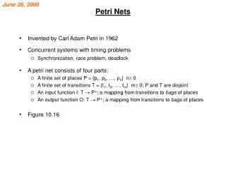
Hardware and Petri nets
E N D
Presentation Transcript
Hardwareand Petri nets Synthesis of asynchronous circuits from Signal Transition Graphs
Outline • Overview of the synthesis flow • Specification • State graph and next-state functions • State encoding • Implementability conditions • Speed-independent circuit • Logic decomposition
Specification(STG) Reachability analysis State Graph State encoding SG withCSC Boolean minimization Next-state functions Logic decomposition Decomposed functions Technology mapping Gate netlist Design flow
x x y y z z z+ x- x+ y+ z- y- Signal Transition Graph (STG)
x y z z+ x- x+ y+ z- y-
xyz 000 x+ 100 y+ z+ z+ x- 110 101 x- x+ y+ z- y- y+ z+ 001 111 y- y+ x- 011 z- 010
xyz 000 x+ 100 y+ z+ 110 101 x- y- y+ z+ 001 111 y+ x- 011 z- 010 Next-state functions
Next-state functions x y z
Simple examples A+ A B+ B A- A input B output B-
Simple examples A+ B+ B A A- B-
Simple examples A+ B- B A A- B+
C Simple examples A+ B+ A C+ C B A- B- C-
C Simple examples A+ B+ A C+ C A- B B- C-
Ro+ Ri+ Ri Ro FIFO cntrl Ao+ Ai+ Ao Ai Ro- Ri- C C Ai- Ao- Ri Ro Ao Ai A FIFO controller
Specification(STG) Reachability analysis State Graph State encoding SG withCSC Design flow Boolean minimization Next-state functions Logic decomposition Decomposed functions Technology mapping Gate netlist
Bus Data Transceiver DSr LDS Device D LDTACK DSr LDS VME Bus Controller DSw LDTACK D DTACK DTACK Read Cycle VME bus
STG for the READ cycle DSr+ DTACK- LDS+ LDTACK+ D+ DTACK+ DSr- D- LDTACK- LDS- D LDS DSr VME Bus Controller LDTACK DTACK
DSr+ DSw+ LDS+ D+ LDTACK+ LDS+ LDTACK- DTACK- DTACK- LDTACK- D+ LDTACK+ DTACK+ D- LDS- LDS- DSr- DTACK+ D- DSw- Choice: Read and Write cycles
Choice: Read and Write cycles DSr+ DSw+ LDS+ D+ LDTACK+ LDS+ LDTACK- DTACK- D+ LDTACK+ LDS- DTACK+ D- DSr- DTACK+ D- DSw-
Circuitsynthesis • Goal: • Derive a hazard-free circuitunder a given delay model andmode of operation
Speed independence • Delay model • Unbounded gate / environment delays • Certain wire delays shorter than certain paths in the circuit • Conditions for implementability: • Consistency • Complete State Coding • Persistency
Specification(STG) Reachability analysis State Graph State encoding SG withCSC Design flow Boolean minimization Next-state functions Logic decomposition Decomposed functions Technology mapping Gate netlist
STG for the READ cycle DSr+ DTACK- LDS+ LDTACK+ D+ DTACK+ DSr- D- LDTACK- LDS- D LDS DSr VME Bus Controller LDTACK DTACK
LDS + LDS = 0 LDS - LDS = 1 Binary encoding of signals DSr+ DTACK- LDS+ LDTACK- LDTACK- LDTACK- DSr+ DTACK- LDS- LDS- LDS- LDTACK+ DSr+ DTACK- D+ D- DTACK+ DSr-
01100 00110 Binary encoding of signals 10000 DSr+ DTACK- LDS+ LDTACK- LDTACK- LDTACK- DSr+ DTACK- 10010 LDS- LDS- LDS- LDTACK+ DSr+ DTACK- 10110 01110 10110 D+ D- DTACK+ DSr- (DSr , DTACK , LDTACK , LDS , D)
ER (LDS+) LDS+ QR (LDS-) LDS- LDS- LDS- ER (LDS-) QR (LDS+) Excitation / Quiescent Regions
LDS+ LDS- LDS- LDS- 10110 10110 Next-state function 0 1 0 0 1 1 1 0
DTACK DSr DTACK DSr D LDTACK D LDTACK 00 00 01 01 11 11 10 10 00 00 01 01 11 11 10 10 Karnaugh map for LDS LDS = 1 LDS = 0 - - - 0 0 - 1 1 - - - - - - - - 1 1 1 - - - - - 0 0 - 0 0 0 - 0/1?
Specification(STG) Reachability analysis State Graph State encoding SG withCSC Design flow Boolean minimization Next-state functions Logic decomposition Decomposed functions Technology mapping Gate netlist
DSr+ DSr+ DSr+ Concurrency reduction LDS+ LDS- LDS- LDS- 10110 10110
Concurrency reduction DSr+ DTACK- LDS+ LDTACK+ D+ DTACK+ DSr- D- LDTACK- LDS-
State encoding conflicts LDS+ LDTACK- LDS- LDTACK+ 10110 10110
CSC+ CSC- Signal Insertion LDS+ LDTACK- LDS- LDTACK+ 101101 101100 D- DSr-
Specification(STG) Reachability analysis State Graph State encoding SG withCSC Design flow Boolean minimization Next-state functions Logic decomposition Decomposed functions Technology mapping Gate netlist
Implementability conditions • Consistency • Rising and falling transitions of each signal alternate in any trace • Complete state coding (CSC) • Next-state functions correctly defined • Persistency • No event can be disabled by another event (unless they are both inputs)
Implementability conditions • Consistency + CSC + persistency • There exists a speed-independent circuit that implements the behavior of the STG(under the assumption that ay Boolean function can be implemented with one complex gate)
a- c+ a 100 000 001 b c b+ b+ Persistency a c b is this a pulse ? Speed independence glitch-free output behavior under any delay
a+ 0000 a+ b+ 1000 b+ 1100 a- a- 0100 c+ c+ 0110 d+ d- d+ 0111 a+ a+ 1111 b- b- 1011 a- c- a- c- 0011 1001 a- c- d- 0001
ab 0000 cd 00 01 11 10 a+ 1000 0 0 0 0 00 b+ 1100 1 0 a- 01 0100 c+ 1 1 1 1 0110 11 d- d+ 0111 1 10 a+ 1111 b- 1011 a- c- 0011 1001 a- c- 0001 ER(d+) ER(d-)
0000 a+ 1000 b+ 1100 a- 0100 c+ 0110 d- d+ 0111 a+ 1111 b- 1011 a- c- 0011 1001 a- c- 0001 ab cd 00 01 11 10 0 0 0 0 00 1 0 01 1 1 1 1 11 1 10 Complex gate
S z C R Implementation with C elements • • • S+ z+ S- R+ z- R- • • • • S (set) and R (reset) must be mutually exclusive • S must cover ER(z+) and must not intersect ER(z-) QR(z-) • R must cover ER(z-) and must not intersect ER(z+) QR(z+)
0000 a+ 1000 b+ 1100 a- 0100 c+ 0110 d- d+ 0111 a+ 1111 b- 1011 a- c- 0011 1001 a- c- 0001 ab cd 00 01 11 10 0 0 0 0 00 1 0 01 1 1 1 1 11 1 10 S d C R
0000 a+ 1000 b+ 1100 a- 0100 c+ 0110 d- d+ 0111 a+ 1111 b- 1011 a- c- 0011 1001 a- c- 0001 but ... S d C R
Assume that R=ac has an unbounded delay 0000 a+ 1000 b+ 1100 a- 0100 c+ R+ disabled (potential glitch) 0110 d- d+ 0111 a+ 1111 b- 1011 a- c- 0011 1001 a- c- 0001 Starting from state 0000 (R=1 and S=0): a+ ; R- ; b+ ; a- ; c+ ; S+ ; d+ ; S d C R
0000 a+ 1000 b+ 1100 a- 0100 c+ 0110 d- d+ 0111 a+ 1111 b- 1011 S a- c- d 0011 1001 C R a- c- 0001 ab cd 00 01 11 10 0 0 0 0 00 1 0 01 1 1 1 1 11 1 10 Monotonic covers
S d C R C-based implementations c d C b a c weak c d weak d a a b generalized C elements (gC)
Speed-independent implementations • Implementability conditions • Consistency • Complete state coding • Persistency • Circuit architectures • Complex (hazard-free) gates • C elements with monotonic covers • ...
y- y- 1001 z- w- 1000 0001 w+ y+ w- z- x+ z- w- w+ 1010 0000 0101 w- y+ x+ z- y+ x+ x- 0010 0100 x- x+ y+ z+ 0110 z+ Synthesis exercise 1011 0011 0111 Derive circuits for signals x and z (complex gates and monotonic covers)
y- 1001 z- w- 1000 0001 w+ y+ w- z- x+ 1010 0000 0101 w- y+ x+ z- 0010 0100 x- x+ y+ z+ 0110 Synthesis exercise 1011 wx yz 00 01 11 10 - 1 0 1 00 0011 - 1 0 1 01 - 0 0 0 11 - 1 1 0 10 0111 Signal x