Download
1 / 1
10 likes | 172 Vues
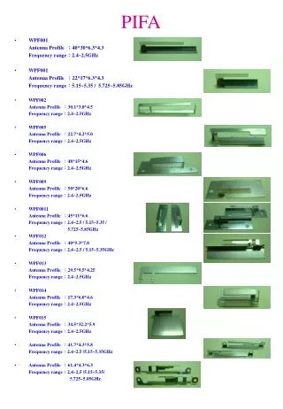
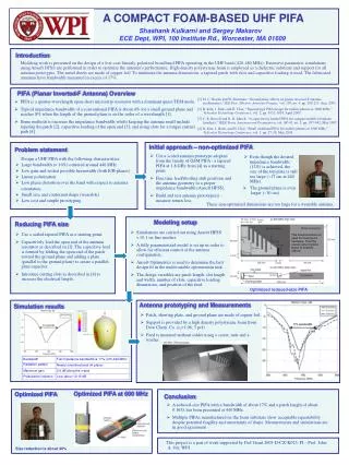
A COMPACT FOAM-BASED UHF PIFA. Shashank Kulkarni and Sergey Makarov ECE Dept, WPI, 100 Institute Rd., Worcester, MA 01609. Introduction.

E N D
A COMPACT FOAM-BASED UHF PIFA Shashank Kulkarni and Sergey Makarov ECE Dept, WPI, 100 Institute Rd., Worcester, MA 01609 Introduction Modeling work is presented on the design of a low-cost linearly-polarized broadband PIFA operating in the UHF band (420-480 MHz). Extensive parametric simulations using Ansoft HFSS are performed in order to optimize the antenna’s performance. High-density polystyrene foam is employed as a dielectric substrate and support for all antenna prototypes. The metal sheets are made of copper foil. To minimize the antenna dimensions, a tapered patch with slots and capacitive loading is used. The fabricated antennas have bandwidth measured in excess of 17%. PIFA (Planar Inverted-F Antenna) Overview [1] M. C. Huynh and W. Stutzman, “Ground plane effects on planar inverted-F antenna performance,” IEE Proc.-Microw. Antennas Propag., vol. 150, no. 4, pp. 209-213, Aug. 2003. [2] B. Kim, J. Park, and H. Choi, “Tapered type PIFA design for mobile phones at 1800 MHz,” Vehicular Technology Conference, vol. 2, pp. 1012-1014, April 2005. [3] C. R. Rowell and R. D. Murch, “A capacitively loaded PIFA for compact mobile telephone handsets,” IEEE Trans. Antennas and Propagation, vol. AP-45, no. 5, pp. 837-842, May 1997 [4] B. Kim, J. Hoon, and H. Choi, “Small wideband PIFA for mobile phones at 1800 MHz,” Vehicular Technology Conference, vol. 1, pp. 27-29, May 2004. • PIFA is a quarter-wavelength open-short microstrip resonator with a dominant quasi-TEM mode. • Typical impedance bandwidth of a conventional PIFA is about 4% for a small ground plane and reaches 8% when the length of the ground plane is on the order of a wavelength [1]. • Some methods to increase the impedance bandwidth whilst keeping the antenna small include tapering the patch [2], capacitive loading of the open end [3], and using slots for a longer current path [4]. Initial approach – non-optimized PIFA Problem statement • Use a scaled antenna prototype adopted from the family of GSM PIFA - a tapered PIFA at 1.8 GHz from [4] as a starting point. • Fine tune feed/shorting stub positions and the antenna geometry to a proper impedance bandwidth (Ansoft HFSS). • Build and test antenna prototype(s) - measure return loss. • Even though the desired impedance bandwidth (12%) is achieved, the size of the top plate is still too large (~17 cm at 440 MHz). Design a UHF PIFA with the following characteristics: • Large bandwidth (> 10%) centered around 440 MHz • Low gain and widest possible beamwidth (both E/H-planes) • Linear polarization • Low phase distortion over the band with respect to antenna orientation • Small size and conformal shape (wearable) • Low cost and simple prototyping • The ground plane is even larger (~30 cm). These non-optimized dimensions are too large for a wearable antenna. Modeling setup Reducing PIFA size • Simulations are carried out using Ansoft HFSS v.10.1 on fine meshes. • A fully parameterized model is set up in order to allow for efficient control of the antenna configuration. • Ansoft Optimetrics is used to determine the best design fit in the multivariable optimization task. • The design variables are patch length, slot length and width, number of slots, capacitive loading dimensions, and position of the feed. • Use a scaled tapered PIFA as a starting point. • Capacitively load the open end of the antenna resonator as described in [3]. The capacitive load is formed by folding the open end of the patch toward the ground plane and adding a plate (parallel to the ground plane) to create a parallel-plate capacitor. • Introduce cutting slots as described in [4] to increase the electrical length. This metal enclosure is used for housing the hardware. Thus the excess ground plane space is properly utilized Optimized reduced-size PIFA Antenna prototyping and Measurements Simulation results • Patch, shorting plate, and ground plane are made of copper foil. • Support is provided by a high density polystyrene foam from Dow Chem. Co. (εr=1.06; 3 pcf). • Feed is mounted without solder using a screw, nuts and a washer. Optimized PIFA at 600 MHz Optimized PIFA Conclusion • A reduced-size PIFA with a bandwidth of about 17% and a patch length of about 0.165l has been presented at 440 MHz. • Multiple PIFAs manufactured on the foam substrate show acceptable repeatability despite potential fragility and uncertainty of shape. Measurements and simulations are in good agreement. This project is a part of work supported by DoJ Grant 2003-IJ-CX-K025, PI – Prof. John A. Orr, WPI Size reduction is about 40%