Enterprise Modeling Methodology for Enterprise Integration
Enterprise Modeling Methodology for Enterprise Integration. 2002. Cheol-Han Kim Ph.D Daejon University, KOREA. Recent Publications. Modeling Methodology Development of Integrated Methodology for Enterprise Engineering, International Journal of CIM, vol.14, No.5, pp.473-488, 2001

Enterprise Modeling Methodology for Enterprise Integration
E N D
Presentation Transcript
Enterprise Modeling Methodology for Enterprise Integration 2002. Cheol-Han Kim Ph.D Daejon University, KOREA
Recent Publications • Modeling Methodology • Development of Integrated Methodology for Enterprise Engineering, International Journal of CIM, vol.14, No.5, pp.473-488, 2001 • Functional Modeling for Enterprise Integration, ICPR 2000, Bangkok, Proceedings CD, 2000.8 • An Integrated Use of IDEF0, IDEF3, and Petri-Net Methods in support of business process modeling, proceedings of institution of mechanical engineers part E- Journal of Process Mechanical Engineering, Vol.215, No.E4, 2001 • The Complementary use of IDEF and UML modeling approaches, submitted to International Journal of Computers in industry • Requirement of EI Framework • Requirements of a Framework for Enterprise Integration, ICPR 16, Praha, Proceedings CD, 2001.7 • Two-phase Modeling for VE • A Two-Phase Modeling Method for Virtual Enterprise, to be presented at IJIE, Busan, KOREA, 2002.10
Contents This is probably just a powerpoint version issue, but my slide here contains nothing.
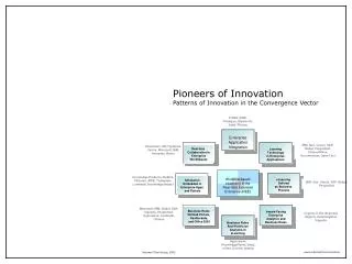
Introduction • Background • Mass Customization on a Global Scale • Is enabled by highly information intensive manufacturing engineering such as CIM, CALS, and EC • Drives close cooperation between partnership enterprises • Requires close interaction and cooperation between business partners despite their geographical distribution • ICEMIT’97 working group developed Generalized Model for partnership enterprise
Introduction process stream sub-process (or activity) nodes n 1 n 3 n 6 n 7 n 8 n 11 n 13 n 1 4 n 15 product application 1 Organization stream product application 2 product application 3 product application 6 product application m company a company b company c company d company e From ICEIMT 97 working group • Describe only one way direction between participants • Does not describe information flow and interactions between participants
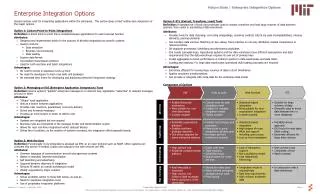
What is Enterprise Integration? • Definition: the task of improving the performance of large complex processes by managing the interactions among the participants • CPC: what is this? between development and manufacturing • Supply Chain : between supplier and manufacture • EI is normally pursed within the context of an emerging, network-centric environment. • Aims at streamlining process, breaking barriers, sharing knowledge, and ? interacting information systems. – http://www.afei.org
What is Enterprise Integration? Distribution Production Planning Assy’s Supplier Part Supplier Customer Product Order Part Order Work Order Product Purchase Order Product Design Part Assy’s Spec. Part Design Sub -Assy’s Enterprise Integration Engineering Process Supply Chain Part
Modeling Methodology • Overview • existing enterprise engineering methodologies: • do not completely address collaboration and interaction. • are less well suited to modelling certain dynamic aspects of partners interactions • Integrated Methodology for Enterprise Engineering (IMEE),developed to meet key aspects of modelling multi-partner enterprises, incorporates two complementary kinds of modelling concept: • process oriented modelling in support of enterprise requirements capture and analysis, centered on ‘function’, ‘activity’ and ‘dynamic systems’ modelling and simulation approaches • object-oriented modelling in support of the conceptual design of multiple business systems, centered on ‘function’, ‘information’ and behaviour modelling.
organization Type main resource output part, product P.A L.A mfg. Facility, human activity resource information, service computing resource, information Information IMEE • Overview - Three axes of enterprise modeling (why 4 bullets below?) • Activity : unit of functionality to perform the business process - Physical activity (PA): deals with the tangible - Logical activity (LA): deals with the intangible • Resource: something required to business process - mfg. facility, human resource, computing resource • Organization: personnel that perform business process • Information : data, fact, or knowledge required to perform the business process
Shop #1 Cutting the material Machine tool process plan machine tool capability Purchase department Internet Issue a purchase order Purchasing requirements supplier’s information Modeling Methodology(IMEE) • Overview - Example [Physical activity] [Logical activity]
Organization Analysis Resource Analysis Function Analysis Information Analysis Modeling Methodology(IMEE) • Overview Business Scenario Matrix Analysis Analysis Repository Organization Design Simulation Process Design Common Data Model Database Design Behavioral Description Design Object-Oriented Approach(UML)
IA Entity vs. Function Matrix OA/RA FA IA Entity vs. Organization Matrix FA OA/RA IA Function vs. Organization matrix Function vs. Resource matrix Resource vs. Organization matrix FA OA/RA IMEE-Analysis • Analysis Phase Information Analysis Business Scenario Function Analysis Organization Analysis Resource Analysis Analysis Matrix/ Repository
IMEE- Analysis Phase • Business Scenario • Objective: Design a scenario for business goal under EI Output Procedure • Design Business scenario • Define major process • Select function area and organization for business scenario • Business scenario • context diagram • Functional area table • Company table • Function vs. organization matrix
IMEE- Analysis Phase • Functional requirements analysis • Objective: To define the functional unit and related object Output Procedure • Define the function • Deduce activity list using map from the function • Decompose the function to unit function level • Describe components of the function • Function definition • Activity list • Functional diagram • Unit function definition • Functional description
Function name Tracking of invoice Description Enterprise code Final assembler (E1) Function code E1-F314 Control Data (source function code) Input data Invoice (I1), vendor (I2) Function Name Function code Input Data (source function code) Output data Invoice status (O1) Output Data Control data Delivery date Material Material Resource Organization Purchase department Organization Resource Organization code E1-O32 Task1 (10 min) Trace invoice Task2 (5 min) Calculate delivery time Operational logic O1 = I1 AND I2 Functional description
IMEE- Analysis Phase • Information Analysis • Objective: To define the entities and relationships Output Procedure • Collect information requirements • Define Subject area – - Product, Order, Production • Integrate views of the unit function output • Describe the entity • Information requirements table • Subject area table • Data dictionary • E-R Diagram (Key level) • Information requirement vs. entity matrix • Function vs. entity matrix
IMEE- Analysis Phase • Resource Analysis • Objective: To define the resource involved Output Procedure • Define the resource (manufacturing, computing, and human) • Allocate resource • Define resource capacity • Analyze resource utilization • Resource table • Resource vs. function matrix
IMEE- Analysis Phase • Organization Analysis • Objective: To define the organization involved Output Procedure • Define organization (Human resource) • Analyze the Organization • Organization table • Organization vs. company matrix • Organization vs. function matrix • Organization vs. entity matrix
IMEE- Analysis Phase • Matrix Analysis • Objective: To verify and valid the analysis result Output Procedure • Analyze matrix • Trace information requirements - Analyze the functional set for the required information • Functional set tracing report
DD Object-oriented model Object-state transition description PD OD DD Distribution & Centralization PD OD DD Simulation - resource capability . Organization . Mfg. Facility - bottleneck function PD OD IMEE- Design Phase • Overview Database Design Repository Process Design Organization Design Object Component
IMEE- Design Phase • Repository Design • Objective: To design the meta-data for modeling component Output Procedure • Define the meta-data for entity, function, resource, organization • Define the relationship between meta-data • Data dictionary for meta- data • Matrix for - Entity vs. function - Function vs. resource - Function vs. organization - Organization vs. resource - Entity vs. organization
MAJOR-PROCESS COMPANY m n has 1 m n n FUNCTIONAL-AREA ORGANIZATION CONTROL-DATA n 1 1 1 n n m ORGANIZATION-DATA UNIT-FUNCTION OUTPUT DATA ENTITY m n 1 1 m n n m n 1 n n RESOURCE RESOURCE-DATA INPUT-DATA 1 SUBJECT-AREA IMEE- Design Phase • Repository Design
IMEE- Design Phase • Process Design • Objective: To define business process with the business scenario Output Procedure • Define major process • Define sub-process • Find the unit function to meet start event and end event • Aggregate the functional set • Combine sub-process • Convert unit function into UOB (Unit Of Behavior) • Functional diagram • Process model - PFD
[Target Process Area] Start event End event direction Repository function vs. resource organization vs. entity organization vs. resource organization vs. function entity vs. function entity vs. Information requirement unit function vs. data matrix Unit function [Matrix] E-R Model [Concept of Process design] IMEE- Design Phase • Process Design
Suggest the spec. (A2-321) C1 inventory (B3-31) C2 Production plan(B3-42) Spec. (A2-321) propose order (A1-221) required order (A3-111) O1 proposed order I2 adjust order (B3-11) I1 Booking order Confirm order (B3-12) order (A1-221) O2 adjusted order Adjusted Spec. Adjusted order Propose the order adjust order Confirm order Suggest the spec. SAND(I1, I2) -> X (O1,O2) 1 2 3 3 B3-11 A2-321 A1-221 A2-321 Object/order X X & & X IMEE- Design Phase • Process Design
IMEE- Design Phase • Common Data Model • Objective: To define the entities and relationships Output Procedure • Integrate views of each entity • Redefine the entities and their attributes • Refine the E-R model • Analyze the Transaction • Design IT platform • Data dictionary • E-R model (Attribute level) • Transaction analysis table • IT platform
IMEE- Design Phase • Behavioral description • Objective: To define behavioral aspect of the UoB Output Procedure • Analyze the behavior of the process • Analyze associations between the UoB • Define the message between UoB • Association table between UoBs • Message table • Method table
IMEE- Design Phase • Simulation • Objective: Find bottleneck functions and resources Output Procedure • Allocate the resource • Convert to the Petri-Net model from process model • Petri-Net model • Bottleneck function list
Control Output Input Function name (FC) Mechanism IMEE- Design Phase • Simulation Function Model Process Model Petri-Net Model resource Mechanism UoB UoB FC Link Junction Arc Transition IO relationship Mechanism Referent Place Function UoB Place [Analogy of modeling component] FC: Function Code
& X & X p3 p1 p6 t1 t3 p5 t4 p2 p4 t2 UOB IMEE- Design Phase • Simulation
IMEE- Design Phase • Organization Design • Objective: Define the organization that executes the business scenario(or are you assigning roles to things in the organization?) Output Procedure • Define organization and role • Design the workflow between organization • Organization table • Information flow between organization
IMEE- Design Phase • Database Design • Objective: Implement the relational table of RDBMS Output Procedure • Select target RDBMS • Translate data dictionary to relational table • Relational table
IMEE- Design Phase • UML Model Generation • Objective: Convert constructs into a UML model for easy implementation Output Procedure • Convert IDEF modeling component into UML component - define Function class & Entity Class - Design Class diagram - Convert IDEF0 & IDEF3 into UML dynamic model • Class Diagram • Use Case diagram • Dynamic Diagram
IMEE- Design Phase • Object-Oriented Approach Main Focus of Modelling UML IDEF Model Context Modelling Constructs Model Context Modelling Constructs Define the problem context Use case diagram Use case, actor, system IDEF0 Context diagram, 0-level functional diagram Design static solution Class diagram Class, relationship IDEF1x Entity, relationship Design dynamic solution State diagram Object, event, state transition, IDEF3 (OSTN) Object, state transition Activity diagram Activity, object transition, decision diamond, Synchronisation bar IDEF3 UoB, junction and link, referent Collaboration diagram Object, link, message IDEF0, IDEF3, Link, referent, unit function, input and output data, mechanism Sequence diagram Object, link, message IDEF0, IDEF3
Requirements of EI Framework • Functional Capability • Requirements • Business functions? (active components?)must co-operate with each other despite being distributed and owned by other enterprises • Functions on EI process must communicate with each other to attain the global goal • Functions and organizations which participate in the business process must be defined when designing business scenario • Interaction between functions following a given scenario must be defined with collaboration rules. • Resources of the business partners must be shared and controlled with business scenario • A Function must respond to other function’s task or result
Requirements of EI Framework • Functional Capability • Definition • Possibility of Cooperating through different functions and organizations from each different company • Ability to carry out certain types of activities, tasks or operations on a business process(why not “ability to produce a certain output”?) • Elements of function capability • Information needed for function execution • Resource available for function execution • Response time required for functional response • Execution time for required time span • Organizationsthat deal with a task ??? • Priority compared with a current task ???
Function A Function A s A Function B Function B Requirements of EI Framework • Function Capability Asynchronous interaction Synchronous interaction • Function B must execute its task with • given scenario, as soon as function B • receive information that we called active • Thus, Function capability of function B • must be considered when function B • receives active information. • Function B execute its task with given • scenario, when function B need to do it • Function capability of function B is not • considered. We called this information • passive
Requirements of EI Framework • Information Hub • Requirements • Business information can be shared between business partners • Data must be accessed through distributed environments • Data defined in EI environment are distributed logically or geographically and user may require information that is located in other database system • Data Schema and Semantic must be represented with common meaning?? • Product Information must be shared between participants for efficient collaboration among set-maker?, suppliers, and customers in order to controls product quality and cost • Because Product information has many different views according to the business partner or business process such as SCM or Engineering process • The semantic of product information must coincide with business partner
Requirements of EI Framework • Information Hub • Definition • Common gateway to support data retrieve from and store into local databases through global database. • Global conceptual schema and local schema are defined • Data allocation is defined
Access control list Data dictionary SQL Gateway ORB IIOP Data Directory Requirements of EI Framework Client Application Server Web Server 2 1 5 Information Hub Global Database 3 4 Local Server Local Server Local Server Local database Local database Local database
Requirements of EI Framework • Information Infrastructure Service • Requirements • Despite heterogeneity, information access must be possible(not sure I captured your thought here). • Interoperability between computing components must be guaranteed • Common business objects, such as suggested by BOMSIG of OMG will support interoperability ??? • Each system must be defined with common representation semantics ??? and syntax • XML will satisfy this requirement • EI environment is possible when the seamless integration of distributed components is guaranteed in spite of heterogeneities between computing resources of the participants
Requirements of EI Framework • Information Infrastructure Service • Definition • Infrastructure Service that supports borderless access and control of distributed systems • IIS will be supported by the following to provide inter-operability: • Business object based on CORBA, DCOM • with business object, Application systems do not need to revised or changed with system expanding, changing, or new construction • Flexible deployment or distribution of application is possible without consideration of each other application • Web service based on XML and SOAP
Two-Phase Modeling • Basic Concept of two-phase modeling Final Assembling Participant of VE Local simulation Functional area Functional element Interaction
XML Two-Phase Modeling • Basic Concept of two-phase modeling Enterprise Modeling event Design Business Scenario Decompose functional area Define Process stream enactment Simulation Local simulation Global simulation YES NO
Current Work • Developing an modeling tool • Support ICEMIT’97 generalized model & IMEE • Define Function/Organization Matrix • In order to decide participants and their functional areas with business scenario • Define Functional Map • In order to extract sub functions or activity with map • Describe Functional Diagram without arrow from Functional Map • Define Information flow adding arrow between functional elements of functional diagram • Describe functional constructs such as resource, organization, execution time, combination logic between input & output • Design and Implement Repository for IMEE case tool • Support process model (IDEF3 & Petri-Net) • Analyze business process • Find bottleneck process • Trace information flow with a specific task
Current Work • VERA (Virtual Enterprise Research and Applications) Forum • Enterprise Modeling • How to describe Business Scenario • Process Modeling Methodology • Information Infrastructure Service • Web service • Community & Communication method • Representation Scheme – ebXML • Virtual Organization • Organize and Evaluate virtual team’s performance
Q & A Thanks for listening to my presentation !!!