CCNA 1 Module 10 Routing Fundamentals and Subnets
550 likes | 955 Vues
CCNA 1 Module 10 Routing Fundamentals and Subnets. Objectives. IP Address . IP Address Grouping. Routed and Routing Protocols. Consider that a packet needs to be sent from node A to node F. How would it decide which path to take?. Routing Protocol vs Routed Protocol. A routed protocol

CCNA 1 Module 10 Routing Fundamentals and Subnets
E N D
Presentation Transcript
Routed and Routing Protocols • Consider that a packet needs to be sent from node A to node F. How would it decide which path to take?
Routing Protocol vs Routed Protocol • A routed protocol • defines the end to end addressing and the packet format of a packet that is forwarded between nodes on different networks. • Internet Protocol (IP) is a routed protocol • A routing protocol • exchanges topology information with adjacent routers to update and maintain their routing tables. • selects the best path through a network RIP is a routing protocol
Routed Protocol • A protocol is a set of rules • A routed protocol is a set of rules that determines how computers at the source and destination communicate with each other across networks • packet format • end to end addressing • In order for a protocol to be routable, it must provide the ability to assign both a network number and a host number for each individual device.
IP is a connectionless, unreliable, best-effort delivery protocol As information flows down the layers of the OSI model, the data is processed at each layer. IP accepts whatever data is passed down to it from the upper layers. Internet Protocol IP
As a frame is received at a router interface. The MAC address is checked to see if the frame is directly addressed to the router interface, or a broadcast. The frame header and trailer are removed and the packet is passed up to Layer 3. The destination IP address is compared to the routing table to find a match. The packet (datagram) is placed in a new frame with the MAC address of the next hop interface. The frame is then transmitted. Network Layer Devices in Data Flow If a match is found or there is a default route, the packet will be sent to the interface specified in the matched routing table statement otherwise packet is discarded
Packets Travel Across Links in a Frame • Packets NEVER travel through the network – they are carried within frames • A new frame MUST be created to carry the packet over each individual link • Routers provide the IP address of the next hop interface (router or host) • The ARP table provides the MAC address of this IP address for the frame destination
Connectionless vs. Connection-Oriented • In a connection oriented system is established between the sender and the recipient before any data is transferred. • example: Telephone • In a connectionless system, the destination is not contacted before a packet is sent. • example: Postal system • TCP is connection oriented • IP is connectionless
The Internet is a huge network where packets are routed according to their IP addresses. IP is unreliable and best-effort as IP does not verify that the data reached its destination and therefore does not resend missing packets. Reliability and resending of packets is handled by the upper layer protocols. IP may be used in conjunction with TCP to add a Layer 4, connection-oriented service that checks for missing segments and resends them to provide reliability. Connectionless Network Services
The IPv4 Packet Header Time-to-live (TTL) Count Decreases with every hop This prevents packets from looping endlessly.
Routing • Routing is an OSI Layer 3 function. • Routers connect networks (or subnetworks) • Routing is the process of finding the most efficient path from one device to another (router) • Routers must maintain routing tables and make sure other routers know of changes in the network topology. This function is performed using a routing protocol to communicate network information with other routers
Routing Through a Network • A router is a network layer device that uses one or more routing metrics to determine the optimal path through the network
Routers Reduce the Size of Broadcast Domains • Routers block LAN broadcasts, so a broadcast storm only affects the broadcast domain from which it originated • Switched networks do not block broadcasts
The difference between a routed and routing protocol – revisited
Routed Vs Routing protocols • A Routed Protocol: • A network protocol suite that provides enough information in its network layer address to allow a router to forward it to the next device and ultimately to its destination. • Defines the format and use of the fields within a packet. • The Internet Protocol (IP) and Novell's Internetwork Packet Exchange (IPX), DECnet, AppleTalk, Banyan VINES, and Xerox Network Systems (XNS) • A Routing Protocol: • Provides processes for sharing route information. Exchange topology info.To determining the best routing paths and transporting packets through an internetwork • Also allows routers to communicate with other routers to update and maintain the routing tables. • Routing Information Protocol (RIP), Interior Gateway Routing Protocol (IGRP), Open Shortest Path First (OSPF), Border Gateway Protocol (BGP), and Enhanced IGRP (EIGRP).
Routing Tables • Routing tables contain the best routes to all known networks. • These routes can be either • Static routes, which are entered manually by the system administrator • Or dynamic routes, which are constructed from information passed between adjacent routers. • A routing table entry contains: • Each Destination • The next hop IP address to reach that destination • The metric for the route via that next hop • Outbound router interface for the next hop
Routing Algorithms and Metrics • Routing protocols have one or more of the following design goals: • Optimization • Simplicity and low overhead • Robustness and stability • Flexibility • Rapid convergence
Interior and Exterior Gateway Protocols • IGPs route data within an autonomous system. • RIP, RIPv2, IGRP, EIGRP, OSPF, IS-IS • EGPs route data between autonomous systems • Border Gateway Protocol (BGP)
Interior Gateway Routing Protocols • Link State and Distance Vector Routing Protocols • Examples of distance-vector protocols: • Routing Information Protocol (RIP) • Interior Gateway Routing Protocol (IGRP) • Enhanced IGRP (EIGRP) • Examples of link-state protocols: • Open Shortest Path First (OSPF) • Intermediate System-to-Intermediate System (IS-IS)
Subnetting • Reasons for subnetting • Provides addressing flexibility for the network administrator. • Each LAN must have its own network or subnetwork address. • Provides broadcast containment and low-level security on the LAN. • Provides some security since access to other subnets is only available through the services of a router.
Introduction to Subnetting • Host bits must are reassigned (or “borrowed”) as network bits. • The starting point is always the leftmost host bit. 3 bits borrowed allows 23-2 or 6 subnets 5 bits borrowed allows 25-2 or 30 subnets 12 bits borrowed allows 212-2 or 4094 subnets
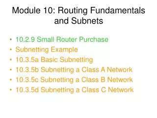
Subnetting Example • This is an example of subnetting the 192.168.10.0 class C network into 8 subnets with 32 host addresses per subnet • Note that the first and last subnets are not used (the first can be) • Also the first and last host address in each subnet are not used
Example Host IP Address from Subnet 2 • The subnet mask is ANDed with the packet address to determine the subnet address - as shown in the next slides