Download
1 / 37
490 likes | 838 Vues
Designing Piles for Drag Force Timothy C. Siegel, P.E., G.E., D.GE with Dan Brown and Associates PC. 43 rd Annual Midwest Geotechnical Conference October 1 – October 3, 2014 Bloomington, Minnesota. Aspects of Axial Resistance of Piles Neutral Plane Concepts

E N D
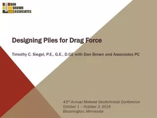
Designing Piles for Drag Force Timothy C. Siegel, P.E., G.E., D.GE with Dan Brown and Associates PC 43rd Annual Midwest Geotechnical Conference October 1 – October 3, 2014 Bloomington, Minnesota
Aspects of Axial Resistance of Piles • Neutral Plane Concepts • Example of Drag Force on Vertical Pile • Downdrag on Batter
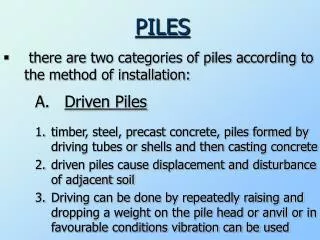
AXIAL RESISTANCE OF PILES Qnominal compression The axial resistance of deep foundations may be divided into two components: @ nominal compression (i.e., FOS = 1) the entire side resistance is positive/upward Negative skin friction doesn’t exist at the geotechnical strength limit state. It is unrealistic to represent drag force as a top load for strength limit analysis. Side resistance (unit value is fside) S Area x fside= Rside 2. Tip resistance Rtip
Fundamentals of Side resistance The shear is confined to a thin zone around the pile and drainage can take place. Therefore, the side resistance is frictional. Burland, J.B. (1973) “Shaft friction in Piles in Clay – A Simple Fundamental Approach” Ground Engineering, 6(3), 30-42. Meyerhoff, G.G. (1976) “Bearing Capacity and Settlement of Pile Foundations” Journal of the Geotechnical Engineering Division, American Society of Civil Engineers, 102, 195-228.
Fundamentals of Side resistance The direction of the (frictional) side resistance is always to resist the tendency for movement. Block Block Friction Friction
Fundamentals of Side resistance The side resistance is fully mobilized at very small relative movements between the pile and soil. less than 1 mm Hanna, T.H. and Tan, R.H.S. (1973) “The behavior of long piles under compressive loads in sand” Canadian Geotechnical Journal, 10(3), 311-340.
Neutral Plane Concepts Fellenius, B.H. (1989) “Unified design of piles and pile groups”, Transportation Research Board, Washington, TRB Record, 1169, 75-82. Fellenius, B.H. (1998) “Recent advances in the design of piles for axial loads, drag loads, downdrag, and settlement” Proceedings, Seminar by ASCE and Ports of New York and New Jersey, 19p.
NEGATIVE SKIN FRICTION …..is side resistance mobilized as the ground moves downward relative to the pile. The magnitude of ground settlement is irrelevant to the development of drag force. Essentially all piles will move relative to the soil as a result of differences in compressibility.* * Fellenius, B.H. Brusey, W.G., and Pepe, F. (2000) “Soil setup, variable concrete modulus and residual load”, ASCE Proceedings, Specialty Conference on Performance Confirmation of Constructed Facilities, 16 p.
Qpermanent DRAG FORCE …..is the axial compressive force induced in a pile due to accumulated negative skin friction.
Neutral plane • …..is the location along the pile where there is no relative movement between the pile and adjacent soil. • The side resistance is negative above the neutral plane. • The side resistance is positive below the neutral plane. • It is the location of the maximum axial compressive stress.
DOWNDRAG ….. is the downward movement of the pile (Spile) resulting from ground settlement.
Permanent (or sustained) loads ….. are constant over time (weight).
transient loads ….. act only a short time (e.g., wind, seismic, traffic).
NEUTRAL PLANE model Qpermanent Profile of Ground Settlement Soil moves downward relative to pile Arrows indicate direction of side resistance Neutral Plane Pile moves downward relative to soil Spile Smax 0 Rtip
NEUTRAL PLANE model Qpermanent Axial Compressive Load in Pile Profile of Ground Settlement Qpermanent Negative Skin Friction Drag Force Arrows indicate direction of side resistance Neutral Plane Positive Side Resistance Spile Smax Rtip 0 0 Rtip
NEUTRAL PLANE METHOD IN DESIGN Important - Ideally, the neutral plane should be determined using the actual, unfactored permanent load.
NEUTRAL PLANE METHOD IN DESIGN Important - Ideally, the neutral plane should be determined using the actual, unfactored permanent load. The neutral plane should be determined using unfactored side/mobilized tip resistances.
NEUTRAL PLANE METHOD IN DESIGN Important - Ideally, the neutral plane should be determined using the actual, unfactored permanent load. The neutral plane should be determined using unfactored side/mobilized tip resistances. The mobilized tip resistance is unknown and must be assumed. Tip resistance versus displacement curves (or t-z curves) may be used in a more refined iterative approach.
NEUTRAL PLANE METHOD IN DESIGN Important - Drag force is not considered when evaluating the geotechnical strength limit state. It is considered in settlement at the geotechnical service limit state and in the structural limit state.
EXample New approach fill Piles are sleeved through fill We want to know the effect of the new approach fill on the existing piles. Compressible soil
Qpermanent EXample This diagram shows that the sustained load, drag force and mobilized resistances are in equilibrium.
Qpermanent EXample Ground Settlement Depth along pile This diagram shows the ground settlement and pile movement…. and the fact that they are the same at the neutral plane. Neutral Plane Pile Movement = Ground Movement at Neutral Plane + Elastic Shortening Penetration of Pile Tip
Qpermanent+ Qtransient Load EXample Sustained Load Plus Cumulative Negative Skin Friction This diagram shows that for the case where the transient load is less than the drag force………. the transient load temporarily “replaces” part of the drag force in the pile. Neutral Plane Max.Force Cumulative Positive Side Resistance Plus Mobilized Tip Resistance Mobilized Tip Resistance Resistance
Downdrag on Batter Piles Takahashi, K. (1985) “Bending of A Batter Pile Due to Ground Settlement”, Soils and Foundations, Japanese Society of Soil Mechanics and Foundation Engineering, Vol.25, No.4, 75-91. Sawaguchi, M. (1989) “Prediction of Bending Moment of a Batter Pile in Subsiding Ground”, Soils and Foundations, Japanese Society of Soil Mechanics and Foundation Engineering, Vol.29, No.4, 120-126. Narasimha Rao, S., Murthy, T.V.B.S.S. and Veeresh, C. (1994) “Induced Bending Moments in Batter Piles in Settling Soils”, Soils and Foundations, Japanese Society of Soil Mechanics and Foundation Engineering, Vol.34, No.1, 127-133. McGuire, M. and Filz (2012) Interim Guidance, Revised LPILE Method to Calculate Bending Moments in Batter Piles for T-Walls Subject to Downdrag, Contract Report W912P8-07-D-0062 for the Army Corps of Engineers.
downdrag on batter piles Ground movement perpendicular to pile Profile of Ground Settlement S to pile = S*sin(q) T Ground surface Batter pile q Smax T S to pile 0 0
downdrag on batter piles Input profile of ground movement perpendicular to pile into LPILE or GROUP The curvature of the profile of ground movement ( ┴ to pile ) determines the moment distribution in the pile .
REVIEW • The “Neutral Plane Method” is accepted by AASHTO; however, the details of its implementation are unclear.
REVIEW • The “Neutral Plane Method” is accepted by AASHTO; however, the details of its implementation are unclear. • The neutral plane method provides a rational framework to consider negative skin friction, drag force, and downdrag(settlement).
REVIEW • The “Neutral Plane Method” is accepted by AASHTO; however, the details of its implementation are unclear. • The neutral plane method provides a rational framework to consider negative skin friction, drag force, and downdrag(settlement). • Negative skin friction does not exist at the geotechnical strength limit state – so it is not realistic to add drag force when determining the required nominal geotechnical resistance.
REVIEW • The “Neutral Plane Method” is accepted by AASHTO; however, the details of its implementation are unclear. • The neutral plane method provides a rational framework to consider negative skin friction, drag force, and downdrag(settlement). • Negative skin friction does not exist at the geotechnical strength limit state – so it is not realistic to add drag force when determining the required nominal geotechnical resistance. • The location of the neutral plane may be where the maximum axial force and is appropriately used to determine the required nominal structural resistance of the deep foundation.
REVIEW • The “Neutral Plane Method” is accepted by AASHTO; however, the details of its implementation are unclear. • The neutral plane method provides a rational framework to consider negative skin friction, drag force, and downdrag(settlement). • Negative skin friction does not exist at the geotechnical strength limit state – so it is not realistic to add drag force when determining the required nominal geotechnical resistance. • The location of the neutral plane may be where the maximum axial force and is appropriately used to determine the required nominal structural resistance of the deep foundation. • The location of the neutral plane is where the ground and pile move together – and so settlement of the ground at the neutral plane is equal to the settlement of the pile.
REVIEW • The curvature of the profile of ground movement ( ┴ to pile ) determines the moment distribution in the pile.
REVIEW • The curvature of the profile of ground movement ( ┴ to pile ) determines the moment distribution in the pile. • The resulting moment distribution usually will not control the pile design. A more critical situation occurs when the curvature of the settlement profile is very large.
THANK YOU FOR YOUR ATTENTION 43rd Annual Midwest Geotechnical Conference October 1 – October 3, 2014 Bloomington, Minnesota