4. REQUIREMENTS ELICITATION
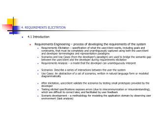
4. REQUIREMENTS ELICITATION. 4.1 Introduction Requirements Engineering – process of developing the requirements of the system

4. REQUIREMENTS ELICITATION
E N D
Presentation Transcript
4. REQUIREMENTS ELICITATION • 4.1 Introduction • Requirements Engineering – process of developing the requirements of the system • Requirements Elicitation – specification of what the user/client wants, including goals and constraints, that must be completely and unambiguously captured using both the user/client and developer terminologies and representation paradigms • Scenarios and Use Cases (from the developer’s paradigm) are used to bridge the semantic gap between the user/client and the developer during requirements elicitation • Requirements Analysis – a model that the developer can unambiguously interpret • Scenarios: Describe a series of interactions between the user the system • Use Cases: An abstraction of a set of scenarios, written in natural language form or modeled diagrammatically • After elicitation, user/client validate the scenarios by testing small prototypes provided by the developer • Testing elicited specifications exposes errors (due to miscommunication or misunderstanding), which are difficult to correct later, and facilitated by user feedback • Scenario development – a methodology for modeling the application domain by observing user environment (task analysis)
4.2 OVERVIEW OF REQUIREMENTS ELICITATION • System Specification – Users identification and subsequent definition of the problem, which serves as the contract between user/client and the developer • System Analysis – a process which formalizes the system specification to produce an analysis model • The only difference between an SS and SA is the language and notation used in their representation – SS is usually in a natural language representation and an SA in a formal or semiformal representation. • An SS document is used for user/client and developer communication • An SA document is used for among developers communication • Both SS and SA focus on user perspective of the system in terms of functionality, interactions between user and the system, errors the system can detect and handle,exceptional cases, the operating environment of the system • See Fig 4-1
Requirements Elicitation system specification :Model Analysis analysis model :Model Figure 4-1. Products of requirements elicitation and analysis (UML activity diagram).
OVERVIEW OF REQUIREMENTS ELICITATION - 2 • Requirements Elicitation Activities • Identifying Actors: developers identify the different types of users of the proposed system • Identifying Scenarios: developers observe users and develop a set of detailed scenarios of system functionality, and use the scenarios to communicate with user to further understanding of the system • Identifying use cases: allows abstract placement of scenarios into scopes • Refining use cases: play-back of scenarios to expose errors, incompleteness, testing exceptional conditions, and demonstration of system behavior • Identifying relationships among use cases: consolidation of use cases to eliminate redundancies and maintain consistency • Identifying nonfunctional requirements: inclusion of constraints that satisfy such measures as performance, documentation, resource specificities, security, quality, safety, reliability, fitness into operating environment
4.3 REQUIREMENTS ELICITATION CONCEPTS • Functional Requirements • Description of interactions between the system and its environment (independent of its implementation) • Example – the SatWatch system’s functional requirements focus on possible interactions between the SatWatch (itself) and its external world (the owner, the GPS, the WebifyWatch API), nothing about its makeup – processor, language, display technology, etc. • Nonfunctional and Pseudo Requirements • Description of user-visible (constraints) aspects, not directly related basic functionality of the system. These include quantitative constraint: performance, response time, accuracy (margin of tolerant error), acceptable range or condition of operation • Pseudo Requirements: • Constraints that restrict implementation platform and language, imported subsystems, and policy issues of user that developer must adhere to
REQUIREMENTS ELICITATION CONCEPTS - 2 • Analysis versus Modeling • Analysis is a modeling activity (formulation process), the model describes the reality of user’s view • Modeling is identifying and classifying real-world phenomena (reality) into concepts • A correct model allows a total mapping of concepts to relevant phenomenon (closure) • A complete model captures or models all phenomenon (total placement into at least one concept) • A consistent model presents a phenomenon in a single, same reality at all times (singularity) • See Fig 4-2
System Model Concept Phenomenon * 1 describes * * Figure 4-2. A System is a collection of real world Phenomena. A Model is a collection of Concepts that represent the System’s Phenomena. Many Models can represent different aspects of the same System. An unambiguous Model corresponds to only one System.
REQUIREMENTS ELICITATION CONCEPTS - 3 • Levels of Description • At the operating environment level - objects that interactions with the target system, including mechanisms for accommodating the dynamics of the changing environment • Levels: • Work division: set of use cases describing the work processes, focusing on the boundaries between the users and the system • Application-specific system functions: set of use cases describing system functions in the application domain • Work-specific system functions: set o fuse cases describing the supporting functions, which are not directly related to the application domain (e.g., supporting DBMS, OS, GUI, management functions, boundary issues like system shutdown, initialization, and exception) • Dialog: set of use cases describing the interactions between users and the user interfaces of the system (focus on control flow and input/output layout issues)
REQUIREMENTS ELICITATION CONCEPTS - 4 • Correctness, Completeness, Consistency, Clarity and Realism • Requirements specification is validated by satisfying these five criteria • Correctness: Every aspect of the model captures a user viewpoint or phenomenon • Completeness: Every possible scenarios is modeled or conceptualized in the specification • Consistency: When the specification contains no contradictions (syntactically and semantically) • Clarity: When the specification is void of ambiguities, that the model mirrors the same system • Realism: Could the system, as specified, be implemented within constraints, otherwise certain assumptions or refinement or reduction of size/complexity is warranted. Typically, rapid prototyping or simulation of complex or high-risk components of the system could be done and evaluated to estimate the extent of realism. • (Ref. Table 4-1)
REQUIREMENTS ELICITATION CONCEPTS - 5 • Verifiability and Traceability • Verifiability – a measure of the (built) system’s ability to repeat (or reproducibility of) the same results for repeated test cases, which meet the user requirements within the given constraints or assumptions • Traceability – a measure of a mapping from system functions onto a set of user requirements through systematic validation of the system design • Classification of Requirement Elicitation Activities • Greenfield Engineering – A non-existing system, spawned by a user need or new markets • Reengineering – Spawned by technology enablers or functional changes, a system is redesigned and reimplemented • Interface Engineering – An existing, or legacy, system is given a new interface subsystem without affecting the system itself
4.4 REQUIREMENTS ELICITATION ACTIVITIES • Requirements elicitation activities constitute a step by step process for mapping the user problem statement into a system specification, formally represented as a set of actors, scenarios, and use cases. • The RE Methods or Activities: • Identifying actors • Identifying scenarios • Identifying use cases • Refining use cases • Identifying relationships among use cases • Identifying participating objects • Identifying nonfunctional requirements
REQUIREMENTS ELICITATION ACTIVITIES - 2 • Identifying Actors – • Actors are entities external to the system itself. Actors interact with the system from outside, defining the classes of functionality or roles. E.g., the GPS, owner, and WebifyWatch are actors to the SatWatch system; or the Dispatcher, FieldOfficer, and Database actors in the FRIEND system • Identifying actors define the boundaries of the system, and the actors define the roles in the organization (from the external point of view or usage of the target system)
REQUIREMENTS ELICITATION ACTIVITIES - 3 • Identifying Scenarios – • Following the actor identification, is the determination of the functionalities or roles of each actor • A scenario is derived from a single user/actor perspective, which represents an informal but concrete description of the actor’s role or a feature of the system • Scenarios are open ended, informal, refineable and depart from the traditional system-centered representations, offering a simplified level of understanding for user/client and developer • Scenarios Types: • As-is scenarios – describe the current situation (esp. for reengineering systems) and relative easy to validate • Visionary scenarios – describe a future system, and useful as a design representation to refine ideas, communication tools for client and developer, or prototyping tool. • Evaluation scenarios – represent user tasks for measuring/evaluating/testing the system • Training scenarios – tutorials for acquainting new users with the system • To identify scenarios, focus is on: tasks from actors’ perspective, info actors need/access, who creates data, what external entities do actors create/change/request for the system, which events impact the actor? • (See Fig 4-5)
REQUIREMENTS ELICITATION ACTIVITIES - 4 • Identifying Use Cases • Scenarios are instances of a use case in that each use case captures a given functionality expressed as a set of scenarios • Each use case is initiated by an actor, and later interacted with by other actors • A use case represents a complete flow of events through the system, describing a series of interactions • A use case can be refined (as in scenarios) through various levels of details • (See Fig 4-6)
REQUIREMENTS ELICITATION ACTIVITIES - 5 • Refining Use Cases • A use case is refined by adding details of roles and interactions of actors • The focus of use case refinement is on completeness and correctness of the specification, by identifying functionalities not previously covered by the sets of scenarios, including rare conditions and exception handling • Refinement of use cases through consolidation and reorganization allows traceability and redundancy in use cases to be removed • Scenarios and Use Case Heuristics: • Use scenarios to communicate with users and to validate functionality • First, refine a narrow vertical slice (I.e., one scenario) to understand the user’s preferred style of interaction • Next, define a horizontal slice (I.e., many not-very-detailed scenarios ) to define the scope of the system • Use mock-ups as a visual support only, user interface design should occur as a separate task once functionality is sufficiently stable • Present the user with multiple alternatives (as opposed to extracting a single alternative from the user) • Detail a broad vertical slice when the scope of the system and the user preferences are well understood.
REQUIREMENTS ELICITATION ACTIVITIES - 6 • Identifying Relationships among Actors and Use Cases • Modeling relationships among actors and use cases reduce complexity and enhances understandability. Three (3) types of relationships are used: • Communication Relationships • Describe the system’s layers of functionality, representing the flow of information from (initiating/sending) actors to use cases that receiving the ‘signals’ and to those actors who receive communication from use cases. Access control (which actor has access to which use case) and event flow are represented in use cases with lines/links • See Fig 4-8
<<initiate>> FieldOfficer OpenIncident Dispatcher ReportEmergency AllocateResources Figure 4-8. Example of communication relationships among actors and use cases in FRIEND (UML use case diagram). The FieldOfficer initiates the ReportEmergency use case and the Dispatcher initiates the OpenIncident and AllocateResources use cases. FieldOfficers cannot directly open an incident or allocate resources on their own.
REQUIREMENTS ELICITATION ACTIVITIES - 7 • Extend relationships between use cases • A use case extends another use case if the extending use case allows separation of exceptional or optional or seldom-occurring flow of events from the base use cases. • The extended use case is functionally complete, with its own entry/exit conditions and provides services to the base use cases • The condition under which the extended use case is initiated is specified in the extended use case as an entry condition • The extended use case is ‘linked’ to the base use case(s) with a broken arrow pointing from the extended use case to the base use case(s) • See Fig 4-9
ConnectionDown FieldOfficer <<extend>> ReportEmergency Figure 4-9. Example of use of extend relationship (UML use case diagram). ConnectionDown extends the ReportEmergency use case. The ReportEmergency use case becomes shorter and solely focused on emergency reporting.
REQUIREMENTS ELICITATION ACTIVITIES - 8 • Include Relationships between use cases • An include use case factors out shared or common behavior among base use cases • Behavior is factored out if it is shared among two or more base use cases, reducing redundancy in the use case models • In the include use case, the conditions under which the included use case is initiated is specified in the base or initiating use cases • The included use case is ‘linked’ to the base use case(s) with a broken arrow pointing from the base use cases to the included use case(s) • See Fig 4-10 and Fig 4-11
<<include>> OpenIncident ViewMap <<include>> AllocateResources Figure 4-10. Example of include relationships among use cases. ViewMap describes the flow of events for viewing a city map (e.g., scrolling, zooming, query by street name) and is used by both OpenIncident and AllocateResources use cases.
REQUIREMENTS ELICITATION ACTIVITIES - 9 • Identifying Initial Analysis Objects • Following agreement on the use of consistent terminologies, developers identify the participating objects for each use case. • The participating objects correspond to the main concepts in the application domain (identified and collated into a glossary by name and description) • The glossary is used in preparing manuals, educate new users and developers • The participating objects constitute the initial analysis model • Heuristics for identifying the participating objects: • Terms that developers or users need to understand the use case • Recurring nouns in the use cases • Real-world entities that the system keeps track of (e.g., resources) • Real-world processes that the system keeps track of • Use cases • Data sources or sinks • Interface artifacts • Using application domain terms
REQUIREMENTS ELICITATION ACTIVITIES - 10 • Aspects and guidelines for identifying or naming participating objects: • If two use cases refer to the same concept, their object names should be the same • If two objects of the same name correspond to two different concepts, one must be renamed • Associating participating objects with use cases: • Which use case creates the object? (I.e., in which use case are object attribute values assigned?) • Which use case modifies or removes the object, and which actor initiates this action? • Is the object relevant to any use case?
REQUIREMENTS ELICITATION ACTIVITIES - 11 • Heuristics for cross-checking use cases, participating objects, and impact of new perspectives • In which use cases are the participating objects defined or entered in the system • Which actors can access these objects, which use cases modify/edit/remove the object • Which actor(s) can initiate the use case • Does every object have at least one association or used in at least one use case • New uses cases developed due to perspective changes can trigger integration or modification of use cases, which may trigger generation or refinement of participating objects and their interactions
REQUIREMENTS ELICITATION ACTIVITIES - 12 • Identifying non-functional requirements • Issues that define non-functional requirements may include: • The look of user-interface or GUI, system response time, deadline requirements, safety and security requirements, size of systems, cost factors, portability • To Elicit Non-functional Requirements, follow: • Interface – kind and level of user’s sophistication • Documentation – level of detail, kind (for user, client, management, technical, process) • Hardware considerations – compatibility issues, hw interactions (esp. for embedded systems) • Performance – system responsiveness, concurrent or single-user support, throughput, load • Error Handling – exceptions (how and who – system or user), effect of operational environ, safety • Quality – level of reliability, availability, fault tolerance, robustness, which the client desires • System changes – extent of it in the future and rationale/responsibility of changes • Physical Environment – operation environment for deployment, external factors (weather/climate) • Security – access limitation and protection, level of security (user, client, manager, operators) • Resources – e.g. memory limitations, power requirements (can impact the kind/size of code to fit the constraints)
MANAGING REQUIREMENTS ELICITATION • Post elicitation activities aimed at: Tools/techniques/steps; agreement with client; validating elicited info - usability testing; reporting or documentation • Tools/Techniques: • Task analysis based on developer’s observation user’s day-to-day performance (The What’s, Why’s – using, e.g., the Knowledge Analysis of Tasks (KAT) tool.) • KAT steps: • identify objects and their associated actions from books, manuals, reports, interviews/observe • Identify procedures (sets of actions), procedure pre- and post-conditions, triggers, scenarios • Identify goals and objectives for each task during interviews, decompose goals into subgoals • Determine the relevance of each object (ordering by significance) toward achieving goals • Construct a model of the task – may use matrix models, tables, cross-referencing techniques
MANAGING REQUIREMENTS ELICITATION - 2 • AGREEING/NEGOTIATING WITH CLIENT • Based on an IBM Joint Application Design (JAD) method for consensus building on requirements elicitation involving all stakeholders in a single session • JAD document content: • Data dictionary, work flows, interface screens • JAD Activities and Products • (See Fig 4-12)
Project definition Management definition guide Research Preliminary specification Session agenda Preparation Figure 4-12. Activities of JAD (UML activity diagram). The heart of JAD is the Session activity during which all stakeholders design and agree to a system specification. The activities prior to the Session maximizes its efficiency. The production of the Final document ensures that the decisions made during the Session are captured. Session script Session Working document Scribe forms Final document preparation Final document
MANAGING REQUIREMENTS ELICITATION - 3 • Validating Elicited Data – Usability Testing • Is the use case model comprehensible to the user/client? • User testing/exploring the requirements data for validation purpose • User interface details (understanding metaphors used) • Approaches: • Classical controlled experiment seeking refutation of hypothesis – empirical analysis of experimental parameters • Usability tests based on evaluating the parameters that define the ease or difficult of use of the system for qualitative purposes • Types of Usability Tests (at the RE phase) • Scenarios – presenting user with visionary scenarios for understanding, accuracy, reaction/acceptance, and realism; cheap, allows rapid feedback, paper-design/sketches done in a prototyping environment • Prototype – actual code segment that exercises system’s (superficial) functionality using vertical testing (depth of a use case) or horizontal testing (focusing on interfaces across many use cases), if carefully done can be reused in actual system; more realistic but expensive • (See Rubin ’94 and Nelsen/Mack ’94 papers)
MANAGING REQUIREMENTS ELICITATION - 4 • Documents Requirements Elicitation • Prepared at when use case model stabilizes, published and baselined • Becomes a deliverable – placed under configuration management • (See RAD table)