Download
1 / 19
190 likes | 209 Vues
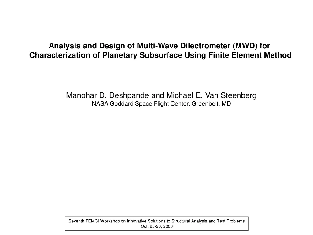
This presentation showcases the use of the Finite Element Method (FEM) to analyze and design the Multi-Wave Dielectrometer (MWD) instrument. The MWD, when integrated with rovers or hoppers on planetary missions, can help in characterizing the electrical properties of the subsurface soil and understanding the geological evolution of planets without the need for digging. The FEM modeling approach is used to estimate mutual capacitances between electrodes, which are then used to develop a probable dielectric profile. The accuracy of the MWD instrument in predicting the dielectric constants of a medium is shown to be greater than 97%.

E N D
Analysis and Design of Multi-Wave Dilectrometer (MWD) for Characterization of Planetary Subsurface Using Finite Element Method Manohar D. Deshpande and Michael E. Van Steenberg NASA Goddard Space Flight Center, Greenbelt, MD Seventh FEMCI Workshop on Innovative Solutions to Structural Analysis and Test Problems Oct. 25-26, 2006
Introduction: Hopper Mission to Moon/Mar Rover Mission to Mar • 1. One of the scientific goals of these missions is to search for water and other • essential materials for human survivability on these planets. • A simple, light weight, and low power instrument called Multi-Wave • Dielectrometer (MWD) if integrated with Rover/Hopper will help in • (a) characterizing electrical properties of subsurface Moon/Mar’s soil, • (b) understanding geological evolution of subsurface of these planets • without digging . • In this presentation an attempt is made to demonstrate use of • Finite Element Procedure to analyze and design proposed • MWD instrument
Multi-Wave Dielectrometer Schematic Diagram of MWD Moon Hopper
Operational Principle of MWD • Data Acquisition • Measure mutual capacitances • between all combinations of • electrodes. Model #1 Data Processing 1.Assume a physical model for stratified medium 2. Using FEM modeling, mutual capacitances are estimated as a function of dielectric profile. 3. Define error function as 4. Using optimization procedure based on gradient based method, Genetic Algorithm (GA), or Neural Network (NN), error is minimized to arrive at a probable dielectric profile. Model #2 FEM Modeling
Finite Element Procedure for Estimation of Mutual Capacitances: How are the capacitances defined? Let and be the charges collected on electrodes #1,#2, #3, and #4 when a low frequency voltage is applied to electrode #1 and other electrodes are grounded. Then capacitances are defined as , , , Other capacitances are similarly defined. In general capacitance is defined as where the charge collected is given by being electrical potential Conclusion: Mutual capacitances can be estimated by solving Laplace’s equation subjected to proper boundary condition dictated by the geometry of MWD instrument. Ground Shield #1 #2 #3 #4 Homogeneous/In-homogeneous medium
Solution of Laplace Equation Using FEM Method Laplace Equation: (1) Electric Field Distribution: (2) Electric energy stored in the structure: (3) For 2-D case: divide the region into triangles (as shown below). If are the nodal voltages then electric potential and field over the triangle can be written as Electric energy stored over the triangle:
Stored energy over the triangle: where If there are N triangles, total stored energy: The nodal voltages are obtained by minimizing the total energy. This minimization yields following matrix equation which can be solved for nodal potentials. Mutual Capacitance:
Flow Chart for Dielectric Profile Estimation Input Electrode Geometry and physical model for medium Using Commercial CAD Package Discretize Geometry Assume Initial Values for electrical properties of medium Estimate Capacitances Using FEM Code Update Initial Guess Estimate Gradient Measured Values of Capacitances Less than desired value Stop
Numerical Validation: Example 1: Geometrical Model Electrode #1 Electrode #4 Electrode #2 Electrode #3 FEM Model
Comparison of computed values of capacitances with earlier published data forward problem
Inversion/Extraction Procedure: Can we extract a dielectric profile of medium if the capacitances between electrodes embedded in the medium are known? Estimation error = 1.4% Estimation error = 1.5% Estimation error = 2.9%
Electrodes Dimensions in cm Ground Shield Electrode Sensor Geometry FEM Model
Example 3: Percentage Error In estimation= 9.5% Percentage Error In estimation= 24%
Ground Shield 4 Electrodes 80 degrees wide FEM Model
Example 4: Layer#1 1. Assume that dielectric constants of layer #1,#3, and #4 are known (=1.0) 2. With er2 = 3.5 generate mutual capacitance data 3. Use the procedure to estimate dielectric constant of layer #2 Layer#2 Layer#3
1. Assume that dielectric constants of layer #1,#2, and #4 are known (=1.0) 2. With er3 = 3.5 generate mutual capacitance data 3. Use the procedure to estimate dielectric constant of layer #3
Conclusions: • 2-Dimensional Finite Element Method has been successfully employed • to analyze and design multi-wave dielectrometer to estimate dielectric • constants of inhomogeneous medium. • When the electrodes are evenly distributed in a medium under test • the multi-wave dielectrometer predicts the medium constants with • accuracy greater than 97% • When the electrodes are distributed on a plane surface, the region • closer to the electrodes are predicted with more accuracy compared • to the regions away from the electrodes. Future Work: • In the present formulation dielectrometer boundary was enclosed in a • closed metallic ground shield. However, in a real situation, ground • shielding is only at the top. We would like to modify our formulation • to take into account actual geometry of MWD • The real MWD is a 3-Dimenional device. Our ultimate goal is to develop • 3-D FEM model to analyze these devices.