Download
1 / 39
440 likes | 623 Vues
Waves, Photons and Medical Physics AS Module 2. 2.1 Waves 2.2 Refraction 2.4 Superposition and Interference 2.5 Diffraction 2.6 Sound. 2.4 Superposition and Interference. You need to be able to:

E N D
Waves, Photons and Medical Physics AS Module 2 • 2.1 Waves • 2.2 Refraction • 2.4 Superposition and Interference • 2.5 Diffraction • 2.6 Sound
2.4 Superposition and Interference • You need to be able to: • 2.4.1 Illustrate the concept of superposition by the graphical addition of two sinusoidal waves • 2.4.4 Understand the significance of coherence as applied to wave sources • 2.4.5 State the conditions for observable interference • 2.4.6 Understand the significance of path difference and phase difference in explaining interference effects • 2.4.7 Describe Young’s slits interference experiment with monochromatic light • 2.4.8 Use the formula ʎ= ay/d applied to Young’s slits experiment. • 2.4.2 Demonstrate knowledge and understanding of the graphical representation of standing waves in stretched strings and air pipes closed at one end • 2.4.3 Identify node and anti-node positions
The Principle of Superposition Two waves are superposed when they are in the same place at the same time and they overlap. The Principle of Superposition defines what the resulting wave should look like: The resultant displacement of the medium at any point in space, is the sum of the displacements that each wave would cause at that point at that time. This principle is used in music to make electronic instruments. The manufacturer determines the frequencies from different instruments e.g. guitar, piano etc. required to give the right sound. These frequencies are then generated electronically and the principle of superposition is used to add them together to make the music. When two waves overlap this is called interference.
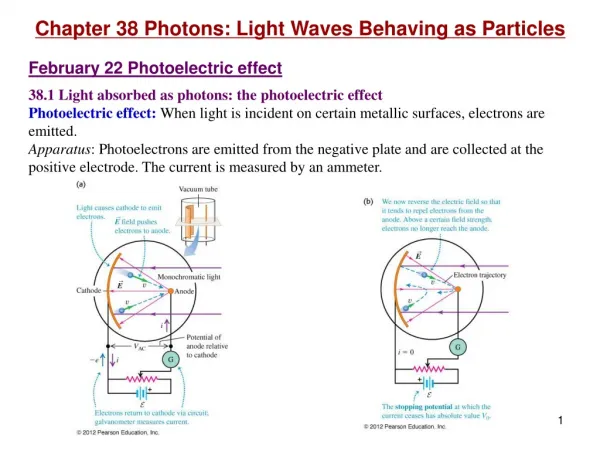
A B C A B C Constructive Interference Example 1: Two identical waves are added together. As they are in phase, the resultant wave is shown. At A: both waves are at crests. So the resultant wave is the amplitude of wave 1 + amplitude of wave 2. At B: both waves are in the middle of an oscillation with zero displacement. The resultant wave is zero as well. At C: Both waves are at troughs. As at A, the resultant wave is the combined amplitude. The two waves have the same frequency and arrive at any point in phase. They have added together to give a bigger resultant wave. This is called Constructive Interference.
Destructive Interference Example 2: Two waves below which are out of phase (or antiphase) are added together. Using the same principle as before, sketch the resultant wave: • This is called Destructive Interference – the 2 waves have cancelled out. • If the two waves were sound waves there would be silence. • If they were light waves there would be darkness.
Example: Page 127 A Displacement Time Displacement B Time C Displacement Time
2.4 Superposition and Interference • You need to be able to: • Illustrate the concept of superposition by the graphical addition of two sinusoidal waves • Understand the significance of coherence as applied to wave sources • State the conditions for observable interference • Understand the significance of path difference and phase difference in explaining interference effects • Describe Young’s slits interference experiment with monochromatic light • Use the formula ʎ= ay/d applied to Young’s slits experiment. • Demonstrate knowledge and understanding of the graphical representation of standing waves in stretched strings and air pipes closed at one end • Identify node and anti-node positions
Coherence • To produce an observable interference pattern you need to have two wave sources that are coherent. • If two sources are coherent, they have the same wavelength or frequency and are exactly in phase or have constant phase difference between them. • The waves produced by coherent sources therefore have: • the same frequency or wavelength • constant phase difference • Whether the coherent sources produce waves that are in phase, antiphase or have some other phase relationship, it does not matter as long as this does not change. Light is a mixture of waves each lasting a short time and emitted by different atoms – the phase is changing all the time. Light from two separate light sources is therefore not naturally coherent and interference will not be observed.
Coherent Sources – (i) Light Coherent Light Sources can be produced using the arrangement shown below: Light first passes through a single slit, and the light is diffracted as shown. This light then passes through a double-slit. These slits act as sources of light waves, just like 2 dippers in a ripple tank. The 2 waves coming from the double slit are coherent, because they both began together at the first slit and therefore have the same wavelength and constant phase difference. S1 Light source S2 Single slit double slit
Coherent Sources (ii) Sound and Radio Waves Coherent Sound and Radio Sources can be produced using the arrangement shown below: Radio frequency generator Signal generator aerials speakers The waves emitted will be either in phase or antiphase, depending upon how the connections are made to the loudspeakers or aerials. The waves are coherent because the loudspeaker or aerial is powered by the same electronic source.
Path Difference In order to determine whether interference at any point is constructive or destructive, you need to find out whether the waves arrive in phase or antiphase. In order to do this, you need to find out the path difference between the two waves. A microwave transmitter can be used to find the path difference between two microwaves. The metal sheet reflects the microwaves from the transmitter. So the receiver will receive two waves: (1) directly from the transmitter and (2) after it has been reflected. Move the position of the metal sheet B A Receiver Transmitter By adjusting the position of the sheet, you can find the position of the maximum signal, or minimum.
Path Difference Metal Sheet Position 1 Position 1:- The reading on the receiver is max. Therefore the signal is a max at B. This is because the wave coming directly from A, and the wave reflected at X are adding together constructively at B X B A Receiver Transmitter Metal Sheet Position 2 Position 2:- As the sheet is moved to position 2, the signal became weaker and then became a max again, at Y. The signal is a max again. Y B A Receiver Transmitter • This means the reflected waves at Position 2 are travelling an extra whole wavelength (to be a max again). So, the path difference between path AXB and AYB is one wavelength (1λ). • When the path difference is a whole no. wavelengths = constructive interference (a max) • When the path difference is an extra ½ wavelength (n + ½λ) = destructive interference (min).
Path Difference Question Y Metal Sheet Position 1 X B A Receiver Transmitter In the experiment above, when the distance AXB is 72.0cm, the signal at B is very strong (a max). The metal sheet is now moved away slowly. The signal at B weakens and then becomes a max again when AYB is 75.1cm. Calculate the wavelength of the microwaves. AYB is exactly one wavelength more than AXB. Therefore the wavelength λ = 75.1 – 72 = 3.1cm.
Interference in communications (i) • We can now identify whether interference from two waves will be constructive or destructive using this principle: • When the path difference is a whole no. wavelengths = constructive interference (a max) • When the path difference is an extra ½ wavelength = destructive interference (min). Example: Radio Waves A signal that reflects off buildings will interfere with the signal that travels straight from a transmitter to a receiver. If the path difference is n+ ½ λ then the signal will be weak (destructive interference) reflected signal direct signal Receiver Transmitter
2.4 Superposition and Interference • You need to be able to: • Illustrate the concept of superposition by the graphical addition of two sinusoidal waves • Understand the significance of coherence as applied to wave sources • State the conditions for observable interference • Understand the significance of path difference and phase difference in explaining interference effects • Describe Young’s slits interference experiment with monochromatic light • Use the formula ʎ= ay/d applied to Young’s slits experiment. • Demonstrate knowledge and understanding of the graphical representation of standing waves in stretched strings and air pipes closed at one end • Identify node and anti-node positions
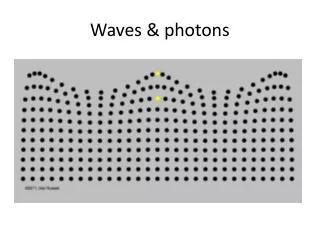
λ λ Wavefronts The central black dot shows the place where the wave starts (the dipper) . Each blue and red circle is a wavefront. The blue circles mark the crests of the waves produced and the red circle the troughs. They are equally spaced, because the distance between each wave-crest and the next, is one wavelength
Two-source Interference We have seen from before two sets of waves could superpose to give constructive or destructive interference. If you investigate the interference pattern produced by two wavefronts (from 2 dippers), you will see a pattern like this: • When the waves are in phase = constructive interference. This is where a crest meets a crest, or a trough meets a trough. You get interference maxima at these points. • When in anti phase = destructive interference, so the waves cancel. This is where a crest meets a trough or a trough meets a crest. You get interference minima at these points. See notes to find these maxima and minima
Two-source Interference – Light Source Consider the interference pattern of two coherent light sources:
Young’s double slit experiment The practical arrangement from before to see light interference patterns was developed in 1801 by Thomas Young. He wanted to use two-source interference to demonstrate that coherent light behaved as a wave. If you use a screen behind the double slit, then you will see a series of stripes or ‘Interference fringes’. Minimum Maximum Minimum (They are called fringes because they look like the fringes on a shawl of blanket) As we have seen, the 2 waves diffract and overlap. Where they overlap there can be constructive interference (a maximum, bright light) or destructive interference (a minimum, darkness).
Spacing for Young Slits If you look at the pattern on the screen from Young slits experiment, what you find is the spacing between one minimum (blank) and the next is a constant value (y). This is the same as the distance between one maximum (bright) and the next: D The diagram is not to scale. The distance s between the two slits might be ¼ mm. The distance D might be a metre. The wavelength of light is so small that the spacing y would be hundreds of wavelengths, while the distance D would be millions of wavelengths. Min Max Min d Max Min y Max Min Under these conditions, you can use this equation for the spacing of maxima or minima for Young’s slits: Separation of fringes, y =Wavelength of light, λ x distance btwn slits and screen separation of two slits, d OR y = λD/d You will not be asked to reproduce this, but may be asked to explain aspects of the derivation.
2.4 Superposition and Interference • You need to be able to: • Illustrate the concept of superposition by the graphical addition of two sinusoidal waves • Understand the significance of coherence as applied to wave sources • State the conditions for observable interference • Understand the significance of path difference and phase difference in explaining interference effects • Describe Young’s slits interference experiment with monochromatic light • Use the formula ʎ= ay/d applied to Young’s slits experiment. • Demonstrate knowledge and understanding of the graphical representation of standing waves in stretched strings and air pipes closed at one end • Identify node and anti-node positions
What is a Standing Wave? What happens when you pluck the string of a guitar? – 2 types of waves are formed: Interference is produced between the 2 waves Progressive transverse wave 1. Longitudinal sound wave The progressive transverse wave is produced when the string is plucked. It travels up the string to the fixed end. It is then reflected back and interferes with the wave travelling towards the fixed end. When these two waves meet, they are added together (superposition of waves) and a STATIONARY or STANDING wave is produced.
Conditions for Standing Waves • A standing wave will be produced when two waves meet • and they are: • The same type • Have the same frequency • Travel in opposite directions in the same medium The waves will have the same velocity and the same wavelength. In most cases they will have almost the same amplitude, so the antiphase waves will totally cancel out.
nodes Anti nodes Nodes and Antinodes • The points that have zero amplitude are called nodes. This is where there is destructive interference between the two waves. • The points that have maximum amplitude are called antinodes. This is where there is constructive interference between the two waves. You can see from this diagram that the distance between two adjacent nodes or antinodes is λ/2
Example Two loudspeakers facing each other emit sound waves of the same wavelength. When a microphone is moved between them, quiet places are observed 20cm apart. What is the wavelength of the sound waves? The quiet places are where there is destructive interference and the sound waves are cancelling each other out – nodes. We know the distance between the nodes is λ/2. So the wavelength of the sound waves: λ/2 = 20cm. Therefore λ = 2 x 20cm = 40cm
Standing Waves using a stretched string A stretched string can be arranged so both ends are fixed. The fixed ends are nodes because they cannot move. Standing waves are formed by interference between waves travelling toward the fixed ends and waves reflected from the fixed ends. At certain frequencies the string will vibrate with a large amplitude. These are resonant frequencies of the system. Resonance occurs when the frequency that is driving the system matches a natural frequency of the system. (remember: child on a swing!)
(resourcefulphysics.org) L M Demonstrating standing waves (1) Standing waves using a string can be demonstrated using a vibration generator and a pulley. The vibration generator moves up and down with a small amplitude and this causes a progressive wave to travel down the string. When the waves meet the pulley end of the string, they are reflected back along the string. So there are two waves of the same wavelength (from the same generator) moving in opposite directions. This produces a standing wave. The different modes of vibration can be seen by increasing the frequency of the vibration generator.
Fundamental Frequency of a stretched string The simplest mode of vibration, where there is only one loop between the fixed ends, is called the fundamental mode. It is also known as the first harmonic vibration. The wavelength of the fundamental is: λ/2 = l where l is the length between the fixed ends λ = 2l
The Resonant Frequencies of a stretched string: The 1st Overtone (2nd Harmonic) If you increase the frequency of the generator, you find that only certain frequencies produce a standing wave. This is because you must have a whole number of standing wave ‘loops’ (for it to be a stationary wave) fitting into the length of the string. The second pattern has two loops. The distance between nodes (or the distance for λ/2 is now ½ l. This is called the 1st overtone, or 2nd harmonic
The Resonant Frequencies of a stretched string: The 2nd Overtone (3rd Harmonic) If the frequency of the system is increased further, the 2nd overtone can be seen (also known as the 3rd harmonic) In this pattern there are three loops. The distance between nodes is now 1/3l. Do you see a pattern emerging vs. harmonics and loops? Fundamental freq = 1st harmonic = 1 loop 2nd harmonic = 2 loops 3rd harmonic = 3 loops Etc………
2. Standing Waves using air columns So, how do we get sound from brass instruments? It is a bit like blowing into a bottle....as you blow into the bottle a standing wave is established. If you change the length of the bottle, the frequency (pitch) of the sound will change. As you blow the longitudinal sound wave travel through the air to the bottom of the bottle where they are reflected to interfere with the sound wave coming into the bottle.
Demonstrating a standing wave (2) Standing waves can be demonstrated using a long glass pipe. The sound waves are generated at the top of the pipe using a loudspeaker attached to a signal generator (to vary the freq). As the frequency of the loudspeaker is increased, the incident wave meets the reflected wave and just like a string, a standing wave is produced to form nodes and antinodes. The resonance tube can be used to show the different modes of vibration, just like a standing wave on a string.
2. Creating the standing wave As the frequency of the initial input wave (you blowing) is increased, the positions of constructive and destructive interference change. N N N N N N N N N N N N The air molecules of the sound waves are vibrating parallel to the direction of the wave. At the closed ends the molecules are not vibrating – these are the nodes. At the open ends, the molecules are vibrating with maximum amplitude – these are the antinodes.
Displacement of the particles Remember these sound waves are longitudinal, so the particles are vibrating parallel to the direction of the propagation of the wave. The particles themselves do not move along the wave from one end to the other. Direction of propagation Displacement Therefore when there is constructive interference the wave particles will vibrate with a greater amplitude. We can then show how the displacement of the particles change throughout the pipe. The right hand (red) line shows the displacement half a period later (when the particle vibrates in the opposite direction).
The modes of vibration in a closed air column (1) The first mode is the first harmonic, or fundamental frequency. This shows λ/4 = L so λ = 4L so fo=v/4L L (2) The second mode is the 3rd harmonic, or 1st overtone. This shows 3λ/4 = L so λ = 4L/3 => f1= 3v/4L (f1=3fo) (3) The third mode is the 5th harmonic, or 2nd overtone. This shows 5λ/4 = L so λ = 4L/5 => f2= 5v/4L (f2 = 5fo) etc..... NB: Node is always at the closed end; Anti node always at the open end.
Varying the length of the air column Up until now we have been talking about changing the frequency of the input sound wave to obtain the different modes of vibration. Now we will keep the frequency constant (e.g. Using a tuning fork) and instead change the length of the air in the pipe. You can do this by (1) changing the length of air by changing the amount of water in the pipe or (2) by putting a tube with two open ends (called a resonance tube) into the pipe and gradually pulling it out, so the length of air is increased.
The positions of resonance As the resonance tube is raised, the sound noticeably gets louder – this happens at the resonance positions, and is where the standing wave is created. The 1st (smallest length) position is the 1st position of resonance and corresponds to the fundamental frequency. These positions of resonance correspond directly with the modes of vibration of a closed air column discussed previously.
Example Draw the fundamental mode of vibration of a stretched string. Label any nodes with a letter N and any antinodes with a letter A. Draw the fourth harmonic (third overtone) for the stretched string. Label any nodes with a letter N and any antinodes with a letter A.