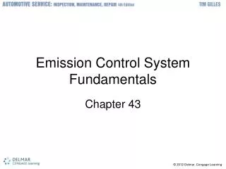
Emission Control Systems
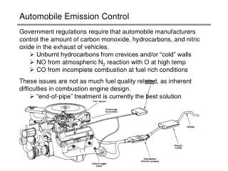
Emission Control Systems. Positive Crankcase Ventilation Thermostatic Air Cleaner Catalytic Converter Evaporative Control System Early Fuel Evaporation Exhaust Gas Recirculation AIR System. Positive Crankcase Ventilation (PCV). Purpose

Emission Control Systems
E N D
Presentation Transcript
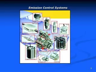
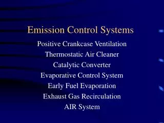
Emission Control Systems Positive Crankcase Ventilation Thermostatic Air Cleaner Catalytic Converter Evaporative Control System Early Fuel Evaporation Exhaust Gas Recirculation AIR System
Positive Crankcase Ventilation(PCV) • Purpose • Eliminate crankcase pressure created by blow by past the cylinder rings (HC’s) • Possible symptoms of a faulty valve • Poor idle • Excessive oil consumption • Oil leaks (oil pan, valve covers etc.) * If a rich condition is being diagnosed check the crankcase for fuel-saturation. If it is saturated with fuel the PCV system will pull these vapors into the intake and cause a rich condition
PCV System • Operation • When the engine is off the valve is seated by the internal spring • When the engine is at idle the valve is pulled open to allow a small amount of flow • When the engine is under load the low vacuum allows the valve to move to a position that allows a high flow rate
PCV Testing • Inspect vacuum lines and grommets for cracks • With engine running pull the PCV valve from the valve cover (an increase in idle speed should be observed) • Plug the PCV valve with your thumb (a decrease in idle speed should be observed) • Replace the PCV valve and remove the oil filler cap • Place a 3x 5 card over the filler (the PCV system is functioning properly if the card is held down tightly) • Seal off the oil filler cap and measure the crankcase vacuum at the dipstick tube • Should be about .5 in/HG
Intake Air Temperature Controls • At low engine temperature fuel has a tendency to puddle in the intake manifold causing poor drivability and warm-up • During certain atmospheric conditions water vapor may freeze in the venturi of a carburetor or on the throttle blades of a throttle body • Intake air temperature control systems are used to better vaporize the fuel and prevent throttle blade icing • Various types of controls are used • Thermostatic air cleaner • Early fuel evaporation (EFE) • Electrical • Heat risers • Heated throttle bodies
Thermostatic Air Cleaner • A thermostat located in the air cleaner directs manifold vacuum to a hot air door vacuum motor when the incoming air is below a preset temperature • During cold weather operation, hot air is pulled from around the exhaust manifold into the engine
Air door is hinged on the white dot and rotates in the direction of the heavy red arrow when the vacuum motor is activated Vacuum Motor Hot Air Door Thermostat Air Cleaner Manifold Vacuum Engine Hot Air Tube Throttle Body Heat Shield Exhaust Manifold
Thermostatic Air Cleaner Testing • Inspect vacuum lines for cracks or improper installation • Inspect exhaust manifold heat shield for rust holes or other damage • Inspect hot air hose for tears • Test vacuum motor with a vacuum pump • Test thermostat for proper operation
Early Fuel Evaporation Systems • Heat risers • Exhaust gas is redirected through a passage in the intake manifold to quickly warm the air/fuel mixture • Promotes good fuel vaporization • Electrical EFE grid • A ceramic heater is placed under the carburetor or throttle body and heats the incoming air/fuel mixture during warm-up
Catalytic Converter • Purpose • 2-way Converter (oxidizing) • Oxidize HC and CO in the exhaust stream into H20 and CO2 • 3-way Converter (reduction) • Converts NOx into N2 and O2 • 2NO => N2 + O2or 2NO2 => N2 + 2O2 • Oxidize HC and CO in the Exhaust stream into H20 and CO2
Catalytic Converter • Components • Oxidation converter • Platinum • Palladium • Reduction Converter • Rhodium • Construction • Pellet • Contains ceramic pellets coated with the catalyst • Monolith • Looks like a honeycomb • The inside of the honeycomb is coated with the catalyst
GM Monolith Converter Pellet Type Converter Pellet Type Converter *Notice the fill plug
Monolith Catalytic Converter Flow Flow A-Reduction Catalyst B-Oxidation Catalyst
Catalytic Converter Testing • Mallet test (only for monolith converters) • Lightly tap on the bottom of the converter if it rattles, it is broken internally • Temperature differential test • Engine should be at operating temperature • Run the engine at a fast idle (2500 RPM) for at least 2 minutes to ensure the converter and O2 sensor are up to operating temperature • Using an infrared pyrometer measure the inlet and outlet temperatures of the catalytic converter • Outlet temperature should be at least 10% higher than the inlet
Catalytic Converter Testing • Upstream vs. downstream O2 (OBD II) • The upstream O2 sensor should be switching from rich to lean • The downstream O2 sensor should be “flatlined” • If the downstream O2 mirrors the upstream O2 it indicates the catalytic converter is inoperative • The ECM monitors this and will set a converter efficiency code if it detects a problem
Evaporative Emissions Control System (EVAP) • On a non-controlled vehicle, evaporative emissions are responsible for 20% of the vehicles total emissions • Evaporative emission systems are designed to control the HC emissions from fuel evaporating from the fuel tank or carburetor float bowl
EVAP System • Components • Fuel tank • Fuel fill cap • Fuel separator • Vapor lines • Charcoal canister • Purge solenoid • Vacuum • Electrical • Float bowl vent
EVAP System • Operation • The fuel tank has a provision to trap some air at the top • The fuel-vapor separator ensures only vapors and not liquid fuel are pushed into the charcoal canister • The charcoal canister stores fuel vapors • The canister purge valve allows manifold vacuum to pull the fuel vapors from the charcoal canister • Engine warm and at part-throttle cruise
EVAP System • Purge solenoid control • May be vacuum or electrical • Vacuum (activated at part throttle when the engine is warmed up) • Attached to ported vacuum • Uses a thermostatic vacuum switch
Ported Vacuum Ported Vacuum
OBDII Purge Solenoid Monitoring • May use a pressure sender in the purge line to verify flow • May look at MAP to see a slight change when flow starts and ends • May look at short term fuel trim to see that the mixture was slightly enriched
Air Injection Reaction System(AIR) • Purpose • During cold startup HC and CO levels are high, the AIR system is designed to help reduce the HC and CO levels by afterburning the exhaust • During normal operation the catalytic converter needs oxygen in order to effectively oxidize the HC and CO, the AIR system supplies extra oxygen to the catalytic converter
Air Injection Reaction System(AIR) • Components • Air pump • Check valve • Diverter valve • Air-switching valve
Air Injection Reaction System(AIR) • Operation • Startup • The AIR system injects air into the exhaust manifold, this creates an “afterburner” effect and helps burn up HC and CO • The additional heat produced by the afterburning helps bring the O2 sensor and catalytic converter up to temperature more quickly • Closed loop operation • The AIR system injects air downstream of the O2 sensor • This prevents a false lean reading • This provides extra oxygen to the oxidizing catalyst
Air Injection Reaction System(AIR) • Operation • Deceleration • The AIR system diverts the air to the air cleaner • During rapid deceleration large amounts of HC are emitted from the engine • If oxygen were injected during deceleration a violent backfire may occur • The diverter valve switches the air to the intake manifold when it sees a high vacuum signal
AIR System Valves • Check valve • Prevents exhaust from flowing into the AIR pump • Diverter valve • This valve determines whether the air will go to the air cleaner or the diverter valve • Under rapid deceleration this valve switches the air to the air cleaner • Air switching valve • Depending on closed/open loop status this valve will direct the air into either the exhaust manifolds or catalytic converter
AIR System Testing • Check vacuum lines and AIR lines for cracks or improper connection (high heat lines must be high silicone rubber) • Check metal lines for rusting (especially connected to catalytic converter) • Unhook AIR line from check valve and see that exhaust is not coming out of the valve • Verify that AIR switching valve is working properly • Open loop – upstream • Closed loop – downstream • Connect vacuum pump to diverter valve and verify that it diverts the air to the air cleaner when vacuum exceeds specified limit
Pulsed Air Injection (PAIR) • Purpose – same as AIR system • Operation • No AIR pump is used, instead the PAIR system relies on the low pressure pulses of the exhaust system to draw fresh air in through a check valve
Exhaust Gas Recirculation (EGR) • Purpose • When combustion temperatures reach between 1500 F and 2500 F NOx is produced • The EGR system allows a small amount of exhaust gases to enter the intake manifold • This dilutes the incoming air/fuel mixture, effectively making it less dense • This slows the burn time down and reduces combustion chamber temperatures • EGR must remain closed during: • Idle • WOT • Cold engine operation
Types of EGR Systems • Types • Vacuum • Backpressure • Electrically controlled vacuum • Digital • Linear
Vacuum EGR • EGR valve contains a vacuum diaphragm which, when vacuum is applied, lifts the EGR valve off of its seat, allowing exhaust gas to enter the intake
Vacuum EGR Control • Ported vacuum is run through a thermostatic vacuum switch to ensure engine is at part throttle and warmed up before the EGR valve opens