Filters
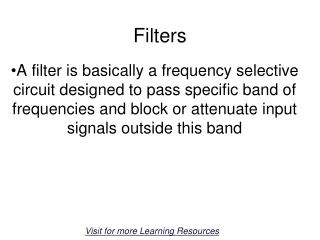
Filters. Filters. Electrical/Electronic filters are electronic circuits which perform signal processing functions, specifically to remove unwanted frequency components from the signal, to enhance wanted ones, or both.

Filters
E N D
Presentation Transcript
Filters Electrical/Electronic filters are electronic circuits which perform signal processing functions, specifically to remove unwanted frequency components from the signal, to enhance wanted ones, or both. Audio equalizers and crossover networks are two well-known applications of filter circuits. Equalizers allow the amplitudes of several frequency ranges to be adjusted to suit the listener's taste and acoustic properties of the listening area. Crossover networks block certain ranges of frequencies( low-frequency signals) from reaching tweeter(high-frequency speakers).
Types of Filters • Electronic Filters belong one of the following types: • Digital Filters • Sampled-data Filters • Continuous-time Filters(Analog Filters) • Electronic filters can also be classified as • Passive filter • Active filter
Types of Analog Filters • The commonly used Analog Filters belong to one of the following types : • Low-pass(LP) • High-pass(HP) • Band-pass(BP) • Band-reject(BR) • All-pass(AP) • Amplitude Equalizer(AE)
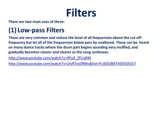
Low-pass(LP) Filter A low-pass(LP) filter is a filter that passes low-frequency signals but attenuates (reduces the amplitude of) signals with frequencies higher than the cutoff frequency. A low-pass(LP) filter is the opposite of a high-pass(HP) filter.
Continuous-timeLP Filter An ideal LP filter completely eliminates all frequencies above the cutoff frequency while passing those below unchanged. Ideal LP frequency response is a rectangular function, and is a brick-wall filter. The transition region present in practical filters does not exist in an ideal filter.
Frequency response of 1st order LP Filter • The gain-magnitude frequency response of a first-order (one-pole) low-pass filter. The voltage gain is shown in decibels .At cut-off frequency there is a 3 dB decline .Angular frequency is shown in units of radians per second.
Stop-band response of LP Filter For a first-order LP filter ,the attenuation rate in the stop-band is 20 dB per decade. A second-order filter attenuates higher frequencies more steeply. In general a second-order Butterworth filter exhibits the 40 dB per decade attenuation rate in the stop-band. Other all-pole second-order filters may roll off at different rates initially depending on their Q-factor, but approach the same final rate of 40 dB per decade. Third- and higher-order filters are defined similarly. In general, the final rate of power roll off for a nth order LP filter is 20n dB per decade.
: Passive RC first order LP filter The combination of resistance and capacitance gives you the time constant of the filter τ = RC (represented by the Greek letter tau)
An active low-pass filter First-order Low Pass Butterworth Filter First-order Low-Pass(LP) Butterworth Filter This 1st-Order low pass Butterworth type filter, consists simply of a passive RC filter connected to the input of a non-inverting operational amplifier. The frequency response of the circuit will be the same as that of the passive RC filter, except that the amplitude of the output signal is increased by the pass band voltage gain of the amplifier. • The gain in the pass band is −R2/R1
An active low-pass filter First-order Low Pass Butterworth Filter Voltage Gain for a First-order Low-Pass(LP) Filter Where AF = the pass band gain of the filter, (1 + R2/R1) ƒ = the Frequency of the Input Signal in Hertz, (Hz) ƒc = the Cut-off Frequency in Hertz, (Hz)
High-pass Filter • A high-pass(HP) filter offers easy passage to high-frequency signal and attenuates the low-frequency signal.
Frequency response of 1st order HP Filter The cutoff frequency for a high-pass filter is that frequency at which the output voltage equals 70.7% of the input voltage. Above the cutoff frequency, the output voltage is greater than 70.7% of the input, and vice versa.
First-order High Pass Butterworth Filter First-order High-Pass(HP) Butterworth Filter Voltage gain of a first-order High-Pass(HP) Filter Where AF = the Pass band Gain of the filter, (1 + R2/R1) ƒ = the Frequency of the Input Signal in Hertz, (Hz) ƒc = the Cut-off Frequency in Hertz, (Hz)
Band-pass(BP) filter • The Band-Pass(BP) filter passes a selected range or band of frequencies that can be either narrow or wide while attenuating all those outside of this range. • The Band-Pass(BP) filter can be of two types: • Broad-band Band-Pass filter • Narrow-band Band-Pass filter
Band-pass(BP) filter Frequency Response of a 2nd order Band-Pass(BP) Filter The term "bandwidth" refers to the difference between the lower cut-off frequency(ƒcLOWER) and the upper cut-off frequency (ƒcUPPER) points.
Active Band Pass Filter Circuit Band-pass(BP) filter A band-pass(BP) filter arrangement commonly consists of a combination of a Low-pass (LP) and a High-pass(HP) filter. 2nd order Band-Pass(BP) Filter
: : Wide-band and narrow-band BP Filter The "Q" of a BP filter is the ratio of the Resonant Frequency, (ƒr) to the Bandwidth(BW) and is given as: In BP Filter, the width of the pass-band between the upper and lower-3dB corner points determine the Quality Factor(Q-point) of the circuit. This Q Factor is a measure of how "Selective" or "Un-selective" the band pass filter is towards a given spread of frequencies. The lower the value of the Q factor the wider is the bandwidth of the filter and consequently the higher the Q factor the narrower and more "selective" is the filter.
Band-Reject(BR) Filter A band-stop filter or band-rejection filterpasses most frequencies unaltered, but attenuates those in a specific range to very low levels. It is the opposite of a band-pass filter. A notch filter is a band-stop filter with a very narrow stop band.(high Q factor).Notch filters are used in live sound reproduction(Public Address systems, also known as PA systems) and in instrument amplifier(especially amplifiers or preamplifiers for acoustic instruments such as acoustic guitar, mandolin etc.) to reduce the noise and unwanted frequencies. e.g., Anti-hum filter is used to filter out the mains hum from a 50 Hz power line, though its higher harmonics could still be present. The filter passes all frequencies, except for the range of 49–51 Hz.
All-pass Filter The all-pass filter is an important building block in audio signal processing systems. It is called all-passbecause all frequencies are passed equally. In other words, the amplitude response of an all-pass filter is any nonzero constant at each frequency, but filter changes the phase relationship between various frequencies. Generally, the first-order all-pass filter is described by the frequency at which the phase shift crosses 90°
Phase response of 1st order All-pass Filter For 1st order all-pass filter ,the amplitude response is flat (within the bandwidth limitation of the amplifier), and there is a 90 degree phase shift at the "corner" frequency.
Applications of All-pass Filters • All pass filters are most often used for following: • for matching phase in systems where phase is important • for producing delays in circuits that need to delay a signal • for creating 90o shifts for quadrature modulators