Download
1 / 39
390 likes | 472 Vues
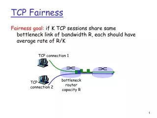
This paper addresses the fairness issue among TCP flows in 802.11b WLANs, proposing an LLC-layer algorithm for fair access to the medium, ensuring short-term fairness to enhance performance.

E N D
Short-term Fairness for TCP Flows in 802.11b WLANs M. Bottigliengo, C. Casetti, C.-F. Chiasserini, M. Meo INFOCOM 2004
Outline • Introduction • Reference Scenario • Scheduling Algorithm Description • Simulation Scenario • Numerical Results • Conclusions • My Comments
Introduction • WLANs using the 802.11b technology add some obstacles to QoS provisioning • Poor channel quality depending on relative position of wireless station (WS) • Interference from hidden terminals • The anomaly due to the different speeds at which WSs transmit
Introduction (cont’d) • This paper addresses the fairness issue among TCP flows • Short-lived flows, representing the majority of today’s Web traffic, suffer from packet losses occurring during or just past the three-way handshake phase • The TCP congestion window size may not be large enough so as to trigger the Fast Recovery algorithm
This paper… • The main contribution of this paper is the proposal of an LLC-layer algorithm that can be implemented on both AP and WSs • The algorithm aims at guaranteeing fair access to the medium to every user, by awarding longer transmission opportunities to WSs that experienced short channel failures
This paper… (cont’d) • The award mechanism works by monitoring the successful medium accesses over a measurement window, and allowing short or long bursts depending on the WS’s history
Reference Scenario • Network and Traffic • Network scenario • Given N wireless stations • N/2 TCP connections in the uplink direction • N/2 TCP connections in the downlink direction
Network scenario Data rate = 11 Mbps
Reference Scenario (cont’d) • Channel Model • An independent error model for each communicating pair of nodes was introduced • An error model is represented by a three-state discrete-time Markov chain
Three-state Error Model Long Bad GOOD Short Bad
Goals of the Scheduling Algorithm • Improve the fairness among wireless stations that may experience location-dependent channel capacity and errors • Provide short-term fairness to TCP traffic in order to enhance the performance of short-lived flows
Scheduling Algorithm Description • At the AP LLC layer, we introduce a separate queue for each WS associated to the AP, while only one queue is implemented at the WS LLC layer • A channel condition estimator is associated to each queue, and transmission is allowed only for the those queues whose channel is estimated to begood
Scheduling Algorithm Description (cont’d) • Upon switching to good channel state, • A queue that has just experienced a bad channel is rewarded with the possibility to send to the MAC layer a maximum number of back-to-back frame (TXburst), • proportional to its forced silence period • The MAC layer will then use the EDCF bursting capability of the current 802.11e draft, to avoid contentions within the burst
Scheduling Algorithm • 1) channel state estimation • 2) queue selection and service • 3) TXburst length setting
Channel State Estimation • Channel State – GOOD • AP receives • A MAC-layer acknowledgment in response to a data frame • A CTS frame in response to an RTS frame • An error-free data frame or RTS
Channel State Estimation (cont’d) • Channel State – BAD • The AP sets the flag to BAD after a transmission failure • The Long Retry Counter (LRC) is incremented when the transmission of a frame longer than the RTS threshold fails due to channel errors • When LRC (SRC) reaches the LRL value, the MAC layer abandons the transmission of the frame and it signals the failure to the LLC layer
Channel State Estimation (cont’d) • Channel State – BAD (cont’d) • We can assume that it is highly like that values of SRC larger than 4 are due to channel errors SRL = 4 LRL = 0
Channel State Estimation (cont’d) • Channel State – PROBE • The AP switches the flag from BAD to PROBE when a configurable value (PTIMER) expires • PTIMER starts to run whenever the channel state switches to BAD • The initial value is doubled (PROBE->BAD) • The value is reset (PROBE->GOOD) • A WS whose queue flag has a PROBE value can transmit a single data frame (RTS) to check the new channel state
Queue Selection Selection NO YES
TXburst Length Setting • The AP has first to compute a fair target throughput (Thr_Fair), that is the throughput value representing the fair service that each WS must receive at a given time (WinLen)
TXburst Length Setting (cont’d) • In order to allow WSs stations to apply the same “controlled” bursty transmission , they need the Thr_Fair value estimated by the AP • Since WSs cannot compute the achieved global throughput • The AP must include the Thr_Fair in control frames that are broadcast on the WLAN (for example, in the Beacon Frame)
Simulation Scenario • Simulations run under the ns-2 simulator • Using ON-OFF source • The average duration of the OFF period is a configurable parameter • The ON duration depends on the amount of bytes to sent • Uniformly chosen among the ones reported in Table III
Simulation Scenario (cont’d) • Transport-layer settings • TCP version is NewReno • The Max. Segment Size (MSS) of TCP segment is equal to 1000 bytes • Data Link-layer settings • Set the RTS threshold at 400 bytes so that TCP ACKs are never using the RTS/CTS handshaking • LLC queue at AP are 400 data frames long at AP
Up/Down Flow Throughput Ratio From : Understanding TCP Fairness over Wireless LAN (INFOCOM 2003)
Numerical Results • Factors • TCP segment Size • WinLen size • Fixed or Dynamic TXburst • Average Off Duration (Traffic Load) • Error Probability
Average Throughput of Uplink Connection Average duration of TCP source OFF period = 1s
Average Throughput of Connection with Different Segments Size
Average Throughput under Different Traffic Load N = 20 Heavy Load
Conclusions • It silences WSs while the channel is unavailable and uses a burst award mechanism to compensate for the missed transmission opportunities • It is highly beneficial for short-lived TCP flows, that normally suffer from losses on their early windows when competing with long-lived flows on a congested link
My Comments • LLC-layer Algorithm, not MAC-layer Algorithm • In 802.11e draft, a TSPEC describes the QoS characteristics of a traffic stream, it can reserve resources within the HC and modify the HC’s scheduling behavior • Delay Bound • Minimum Burst Size • Service Interval