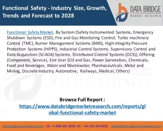
Functional Safety Demystified
Functional Safety Demystified. September 2011 Bob Weiss Principal Consultant Honeywell Process Solutions bob.weiss@honeywell.com. Outline. What is Functional Safety? SIS, SIF and SIL Standards AS IEC61508 and AS IEC61511 An example to demonstrate compliance

Functional Safety Demystified
E N D
Presentation Transcript
Functional Safety Demystified September 2011 Bob WeissPrincipal ConsultantHoneywell Process Solutions bob.weiss@honeywell.com
Outline • What is Functional Safety? • SIS, SIF and SIL • Standards AS IEC61508 and AS IEC61511 • An example to demonstrate compliance • 4.5 day TÜV FSEng course in 45 minutes!
What is Functional Safety? • Part of Overall Safety • freedom from unacceptable risk • Achieved by a Safety Instrumented System (SIS) • E/E/PE Safety System in IEC61508 • Examples: • Emergency Shutdown System • Burner Management System • Includes field devices as well as logic solver • A SIS places or maintains a process in a safe state • Process = Equipment Under Control (EUC) in IEC61508 • Implements Safety Instrumented Functions (SIFs) • Each SIF achieves a Safety Integrity Level (SIL) • Acronyms to remember: SIS, SIF and SIL !.
Temperature transmitter SIF 1: TZH1234 SIL 2 Solenoid Shut-off valve Temperature transmitter SIL 1 SIF 2: PZHH1234 Logic Solver (Safety PLC) PressureTransmitter Relayin MCC Solenoid Globe valve Flow transmitter Safety Instrumented System - SIS Some terms: SIS, SIF and SIL Safety Instrumented Function - SIF Safety Integrity Level - SIL
Why Functional Safety? • Buncefield, England 11 Dec 2005 • Storage tank level gauge showed constant reading • High level alarm switch jammed • Gasoline tank overflowed • Mist exploded • Largest explosion in peacetime • 20 tanks on fire • Burned for three days • Significant environmental impact • Millions of pounds damage.
61511 61511 61508 61508 61511 61508 Standards: IEC61508 or IEC61511 ? AS/IEC 61508 SISComponent Manufacturers AS/IEC 61511 SISIntegrators & Users OR SIL4APPLICATIONS
IEC61511 Safety Lifecycle Management of functional safety and functional safety assessment and auditing 10 9 Safety life-cycle structure and planning 1 Hazard and risk analysis 11 Verification 2 Allocation of safety functions to protection layers Safety requirements specification for the safety instrumented system 3 Design and development of other means of risk reduction Engineering Contractor 4 Design and engineering of safety instrumented system SIS Vendor 5 Installation, commissioning and validation Operation and maintenance 6 End User 7 Modification 8 Decommissioning
Complying with AS IEC 61508 & AS IEC 61511 • Target SIL must be specified for each SIF based on hazard and risk analysis • Processes for SIS throughout lifecycle must comply • Each SIF must meet target SIL requirements for: • Architectural constraints • Random failure rate (PFDave) • Development process for each component • Field devices, logic solver, shutdown valves etc. • Not just TÜV certification • Though it helps ! • Not just meeting PFDavg target.
Comply Throughout Lifecycle • For the rest of the presentation we’ll follow the SIS lifecycle • What do we need to do to comply at each stage? • See the following example… • Only the main elements of compliance are covered.
1 Hazard and Risk Analysis 10 Management of functional safety and functional safety assessment and auditing Safety life-cycle structure and planning 9 1 Hazard and risk analysis 11 Verification • Output is a list of hazardous events with their process risk and acceptable risk. 2 Allocation of safety functions to protection layers Safety requirements specification for the safety instrumented system 3 Design and development of other means of risk reduction 4 Design and engineering of safety instrumented system 5 Installation, commissioning and validation Operation and maintenance 6 Modification 7 Decommissioning 8
Case Study: 1 A Hazard • “potential source of harm” • 300t of Liquefied Petroleum Gas can potentially cause harm • Hazardous Event Example: BLEVE YouTube .
H Case Study: 2 HazOp • Node: LPG Tank • Guideword: HIGH LEVEL • Consequence: High Pressure, possible tank rupture & major fire • Existing Controls: Pressure Relief Valve (PSV-1) • New Controls: Add High Level Alarm.
2 Allocation of Safety Functions • Often called SIL Analysis or SIL Determination • Output is a list of Safety Instrumented Functions together with their required Safety Integrity Level. 10 Management of functional safety and functional safety assessment and auditing Safety life-cycle structure and planning 9 1 Hazard and risk analysis Verification 11 Allocation of safety functions to protection layers 2 3 Safety requirements specification for the safety instrumented system Design and development of other means of risk reduction Design and engineering of safety instrumented system 4 5 Installation, commissioning and validation 6 Operation and maintenance Modification 7 8 Decommissioning
Case Study: 3 Design after HazOp • Is Risk acceptable?
Consequence severity Major Medium Increasing Risk Minor Likelihood of occurrence LOW MEDIUM HIGH Risk The product of severity and likelihood
Case Study: 4a Risk Reduction Hazard - 300t of LPG Level stable Process under control Control valve sticks Process deviation or disturbance LAH Alarm Level Increasing Process out of control High Pressure Hazardous situation PSV Vessel fails Hazardous event Impact / Consequence 300t of boiling LPG released -likely major fire and fatalities
Risk Reduction Control System (BPCS) Process Risk Analysis - Layers of Protection 1 Mechanical PSV Target:1 per 10,000y X 100 Hazardous Event !! AlarmLAH X 1 ! Required:X 10,000 Only havex 100 !! Hazardous Situation : 1 per y
Case Study: 4b Risk Reduction Hazard - 300t of LPG Level stable Process under control Control valve sticks Process deviation or disturbance LAH Alarm Level Increasing Process out of control LZHH Trip High Pressure Hazardous situation PSV Vessel fails Hazardous event Impact / Consequence 300t of boiling LPG released -likely major fire and fatalities
Case Study: 5 Add a SIF • High Level Trip LZHH2 added • Shuts off flow when High High level reached.
Risk Reduction Control System (BPCS) Process SIL Determination 1 - Layers of Protection Mechanical PSV Target:1 per 10,000y X 100 SIF LZHH Hazardous Event !! SIL 2 X 100 AlarmLAH Required:X 10,000 SIF must reduce risk by10,000/100 = 100 Hazardous Situation : 1 per y
SafetyAvailability Probability of Failureon Demand (PFDavg) SIL 4 ≥ 10-5 < 10-4 > 99.99% 3 ≥ 10-4 < 10-3 99.9 - 99.99% 2 ≥ 10-3 < 10-2 99 - 99.9% 1 ≥ 10-2 < 10-1 90 - 99% - Safety Integrity Level vs. Risk Reduction Risk ReductionFactor > 10,000 1,000- 10,000 100- 1,000 10- 100 (Control ≤ 10) = 1 - PFDavg = 1 / RRF Used later for verifying SIL achieved
SIL is more than just PFD • Target SIL must be specified for each SIF based on hazard and risk analysis • Processes for SIS throughout lifecycle must comply • Each SIF must meet target SIL requirements for: • Architectural constraints • Random failure rate (PFDave) • Development process for each component.
3 Safety Requirements Specification - SRS • Defines functional and integrity requirements of SIS • Output is set of documents ready for detail design. 10 Management of functional safety and functional safety assessment and auditing Safety life-cycle structure and planning 9 1 Hazard and risk analysis Verification 11 Allocation of safety functions to protection layers 2 3 Safety requirements specification for the safety instrumented system Design and development of other means of risk reduction Design and engineering of safety instrumented system 4 5 Installation, commissioning and validation 6 Operation and maintenance Modification 7 8 Decommissioning
Cause-and-Effect Diagram • SIFs commonly documented byCause and Effect diagrams • Could include required SIL.
4 Design and Engineering • SIS vendor for logic solver • EPC contractor or end-user for field hardware. 10 Management of functional safety and functional safety assessment and auditing Safety life-cycle structure and planning 9 1 Hazard and risk analysis Verification 11 Allocation of safety functions to protection layers 2 3 Safety requirements specification for the safety instrumented system Design and development of other means of risk reduction 4 Design and engineering of safety instrumented system 5 Installation, commissioning and validation 6 Operation and maintenance Modification 7 8 Decommissioning
Standards Compliance • Target SIL must be specified for each SIF based on hazard and risk analysis • Processes for SIS throughout lifecycle must comply • Each SIF must meet target SIL requirements for: • Architectural constraints • Random failure rate (PFDave) • Development process for each component.
FS Management System - TÜV Certification • See HPS TÜV Certificate • Covers compliance to IEC 61508 & IEC 61511 • Periodic audits and renewal • Need comparable processes for other phases.
Standards Compliance • Target SIL must be specified for each SIF based on hazard and risk analysis • Processes for SIS throughout lifecycle must comply • Each SIF must meet target SIL requirements for: • Architectural constraints • Random failure rate (PFDave) • Development process for each component.
Case Study: 6 PFD Calculation • What is calculated PFDave for SIF LZHH2?. SIL 2
SafetyAvailability Probability of Failureon Demand (PFDavg) Risk ReductionFactor SIL 4 ≥ 10-5 < 10-4 > 99.99% >10,000 3 ≥ 10-4 < 10-3 99.9 - 99.99% 1,000 - 10,000 2 ≥ 10-3 < 10-2 99 - 99.9% 100 - 1,000 1 ≥ 10-2 < 10-1 90 - 99% 10 - 100 - (Control < 10) Safety Integrity Level vs. PFDave = 1 - PFDavg = 1 / RRF Implementation Focus
Approximation to PFDave 1 Probability itemhas failed PFD(t) ~ ~ PFD average time t 0 TI = test interval PFDaverage = lDU TI / 2 where lDU= Dangerous Undetected failure rate Remember this!
Case Study: 6 PFD Calculation • Test interval = 1 y • Reliability data: • Valve: λDU = 1/10y (= 0.1 y-1) • Logic solver: λDU = 1/1000y (= 0.001 y-1) • Sensor: λDU = 1/100y (= 0.01 y-1) • PFDave = λDU x TI / 2 = 0.1 x 1 / 2 = 0.05 for valve 0.001 x 1 / 2 = 0.0005 for logic solver 0.01 x 1 / 2 = 0.005 for transmitterTotal PFDave = 0.05 + 0.0005 + 0.005 = 0.0555 • Calculated SIL = 1 (PFDave range 0.01 – 0.1) • Required SIL = 2 Not OK! • How can this be fixed?
Effect of Test Interval on PFDave 1 Probability itemhas failed PFD(t) ~ ~ ~ ~ Average PFD 0 TI (Test Interval) 1 PFD(t) Average PFD 0 TI TI TI TI time t
Case Study: 7a Adjust Test Interval • Test interval = 1 month • Reliability data: • Valve: λDU = 1/10y (= 0.1 y-1) • Logic solver: λDU = 1/1000y (= 0.001 y-1) • Sensor: λDU = 1/100y (= 0.01 y-1) • PFDave = λDU x TI / 2 = 0.1 / 12 / 2 = 0.004 for valve 0.001 / 12 / 2 = 0.00004 for logic solver 0.01 / 12 / 2 = 0.0004 for transmitterTotal PFDave = 0.004 + 0.00004 + 0.0004 = 0.00444 • Calculated SIL = 2 (PFDave range 0.001 – 0.01) • Required SIL = 2 OK • BUT operations object to monthly testing !.
Case Study: 7b Duplicate Block Valves • Test interval = 1 year • Reliability data: • Valve: λDU = 1/10y (= 0.1 y-1) • Logic solver: λDU = 1/1000y (= 0.001 y-1) • Sensor: λDU = 1/100y (= 0.01 y-1) • For 2 valves 1oo2 voting: PFDave = (0.1 x 1 / 2)2 = 0.0025 • PFDave = 0.0025 + 0.0005 + 0.005 = 0.0080 • Calculated SIL = 2 (PFDave range 0.001 – 0.01) • Required SIL = 2 OK .
Standards Compliance • Target SIL must be specified for each SIF based on hazard and risk analysis • Processes for SIS throughout lifecycle must comply • Each SIF must meet target SIL requirements for: • Architectural constraints • Random failure rate (PFDave) • Development process for each component. Is one transmitter enough or do we need two?
Architectural Constraints • Aim is to avoid unrealistic reliability claims • From single devices (“elements”) • Constrains SIF architecture based on: • Safe Failure Fraction • Complexity of device (“Type A” or “Type B”) • Target SIL • Outcome is required Hardware Fault Tolerance • No. of voted devices minus 1 (typically) • Use Tables in IEC61508 part 2 • IEC61511 has simplified requirements.
Undetected SAFE Closes spontaneously due to loss of energy Detected by voltage control Detected by diagnostics DANGEROUS Stuck at open Undetected Safe Failure Fraction • Safety valve, normally open & normally energized • In case of an out of control process, the valve has to close SAFE
Architectural Constraints – IEC61508.2 TypeA subsystems – e.g. pressure switch Table 2: Safe failure fraction Hardware fault tolerance 0 1 2 < 60 % SIL1 SIL2 SIL3 60 % - 90 % SIL2 SIL3 SIL4 90 % - 99 % SIL3 SIL4 SIL4 ≥ 99 % SIL3 SIL4 SIL4 TypeB subsystems – e.g. Logic Solver, Smart Tx Table 3: Safe failure fraction Hardware fault tolerance 0 1 2 < 60 % Not allowed SIL1 SIL2 60 % - 90 % SIL1 SIL2 SIL3 90 % - 99 % SIL2 SIL3 SIL4 ≥ 99 % SIL3 SIL4 SIL4 Independent Channels Required = Hardware Fault Tolerance + 1
Case Study: 8 Architectural Constraints • Transmitter LZT 2 is a smart radar gauge • Can we use single transmitter to satisfy SIL 2? • Must also check for logic solver and valve.
TypeB subsystems – e.g. Logic Solver, Smart Tx Table 3: Safe failure fraction Hardware fault tolerance Std Tx 0 1 2 < 60 % Not allowed SIL1 SIL2 60 % - 90 % SIL1 SIL2 SIL3 LTZ 2 90 % - 99 % SIL2 SIL3 SIL4 ≥ 99 % SIL3 SIL4 SIL4 Case Study: 8 Architectural Constraints • Smart Transmitter = Type B device • Use Table 3 in IEC61508.2 • Safe Failure Fraction = 91.8% • From TÜV Certificate • For SIL 2, required Hardware Fault Tolerance = 0 • Therefore one transmitter is ok for SIL 2.
Architectural Constraints for Logic Solver • E.g. Honeywell FSC and Safety Manager logic solvers • 1oo2D architecture OR 2oo4D architecture • All have 99% safe failure fraction • Hence all are “SIL 3 capable” • 2oo4D has lower spurious trip rate, but costs more. TypeB subsystems – e.g. Logic Solver, Smart Tx Table 3: Safe failure fraction Hardware fault tolerance 0 1 2 < 60 % Not allowed SIL1 SIL2 60 % - 90 % SIL1 SIL2 SIL3 90 % - 99 % SIL2 SIL3 SIL4 FSC, SM ≥ 99 % SIL3 SIL4 SIL4
Standards Compliance • Target SIL must be specified for each SIF based on hazard and risk analysis • Processes for SIS throughout lifecycle must comply • Each SIF must meet target SIL requirements for: • Architectural constraints • Random failure rate (PFDave) • Development process for each component How likely is it that each component is free from systematic faults (“bugs”) ?
Case Study: 9 – Transmitter Selection • Must control systematic faults • Transmitter selected must comply with IEC61508 and IEC61511 • Must either be: • Proven in use: • Comparable application • Sample size sufficient for 70% confidence level • All failures documented or • Designed and manufactured in accordance with IEC 61508 • Confirmed by independent certificate (e.g. by TÜV) • “SIL x Capable”.
Standards Compliance • Target SIL must be specified for each SIF based on hazard and risk analysis • Processes for SIS throughout lifecycle must comply • Each SIF must meet target SIL requirements for: • Architectural constraints • Random failure rate (PFDave) • Development process for each component • Design now complies.
5 Installation, Commissioning, Validation • Logic Solver installed with field equipment • Includes loop checking, validation and final functional safety assessment. 10 Management of functional safety and functional safety assessment and auditing Safety life-cycle structure and planning 9 1 Hazard and risk analysis Verification 11 Allocation of safety functions to protection layers 2 3 Safety requirements specification for the safety instrumented system Design and development of other means of risk reduction Design and engineering of safety instrumented system 4 5 Installation, commissioning and validation 6 Operation and maintenance Modification 7 8 Decommissioning
Standards Compliance • Target SIL must be specified for each SIF based on hazard and risk analysis • Processes for SIS throughout lifecycle must comply • Each SIF must meet target SIL requirements for: • Architectural constraints • Random failure rate (PFDave) • Development process for each component • Verification, Validation, Functional Safety Assessment.
Case Study: 10 Verification and Validation • Verification and Validation Plan for project • V&V Plan Template • SIL 2 independence required (i.e. independent engineer) • Define responsibilities • Verify Safety Requirements Specification • Verify hardware design documents • Verify functional specifications etc • Implement code walkthrough • Logic Solver Factory Acceptance Test • Complete integration test of application software on target hardware • Logic Solver Site Acceptance Test • Power up test on site • Safety Function Testing • Functional Safety Assessment.