PROGRAMMING THE BASIC COMPUTER
Understand the fundamentals of programming a computer, starting from machine language to assembly language. Learn about writing instructions, program execution, and the hierarchy of programming languages.

PROGRAMMING THE BASIC COMPUTER
E N D
Presentation Transcript
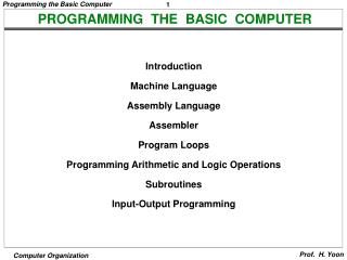
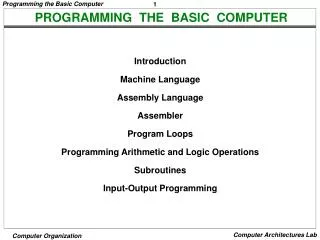
PROGRAMMING THE BASIC COMPUTER Introduction Machine Language Assembly Language Assembler Program Loops Programming Arithmetic and Logic Operations Subroutines Input-Output Programming
A total computer system includes both hardware and software. Writing a program for a computer consists of specifying, directly or indirectly, a sequence of machine instructions. Machine instruction inside the computer from a binary pattern. It is preferable to write a program with the more familiar symbols of the alphanumeric character set. A program written by a user may be either dependent or independent of the physical computer that runs his program. INTRODUCTION
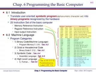
Introduction Instruction Set of the Basic Computer m: effective address M: memory word (operand) found at m Symbol Hexadecimal Code Description • AND 0 or 8 AND M to AC • ADD 1 or 9 Add M to AC, carry to E • LDA 2 or A Load AC from M • STA 3 or B Store AC in M • BUN 4 or C Branch unconditionally to m • BSA 5 or D Save return address in m and branch to m+1 • ISZ 6 or E Increment M and skip if zero • CLA 7800 Clear AC • CLE 7400 Clear E • CMA 7200 Complement AC • CME 7100 Complement E • CIR 7080 Circulate right E and AC • CIL 7040 Circulate left E and AC • INC 7020 Increment AC, carry to E • SPA 7010 Skip if AC is positive • SNA 7008 Skip if AC is negative • SZA 7004 Skip if AC is zero • SZE 7002 Skip if E is zero • HLT 7001 Halt computer • INP F800 Input information and clear flag • OUT F400 Output information and clear flag • SKI F200 Skip if input flag is on • SKO F100 Skip if output flag is on • ION F080 Turn interrupt on • IOF F040 Turn interrupt off
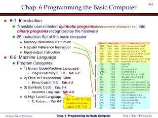
Machine Language MACHINE LANGUAGE • A Program is a list of instructions or statements for directing the computer to perform a required data processing task. • There are various types of programming languages that one may write for a computer, but the computer can execute programs only when they are represented internally in binary form. • Programs written in other language must be translated to the binary representation of instruction before they can be executed by the computer.
Hierarchy of programming languages: Programs written for a computer may be in one of the following categories:- Machine-language - Binary code - Octal or hexadecimal code Assembly-language (Assembler – Symbols to binary) - Symbolic code High-level language (Compiler – High level language program to binary) MACHINE LANGUAGE
Strictly speaking a machine language program is a binary program. (It is customary refer to octal or hexadecimal code because of the simple equivalency between binary and octal or hexadecimal). Because of the one-to-one relationship between a symbolic instruction and its binary equivalent, an assembly language is considered to be a machine-level language. MACHINE LANGUAGE
0 0010 0000 0000 0100 1 0001 0000 0000 0101 10 0011 0000 0000 0110 11 0111 0000 0000 0001 100 0000 0000 0101 0011 101 1111 1111 1110 1001 110 0000 0000 0000 0000 ????????? Location Instruction Code
Machine Language COMPARISON OF PROGRAMMING LANGUAGES • Binary Program to Add Two Numbers • Hexa program Location Instruction Instruction code – binary content of the location Location Instruction Code 000 2004 001 1005 002 3006 003 7001 004 0053 005 FFE9 006 0000 0 0010 0000 0000 0100 1 0001 0000 0000 0101 10 0011 0000 0000 0110 11 0111 0000 0000 0001 100 0000 0000 0101 0011 101 1111 1111 1110 1001 110 0000 0000 0000 0000 Location – memory Location • Program with Symbolic OP-Code • Assembly-Language Program • ORG 0 /Origin of program is location 0 • LDA A /Load operand from location A • ADD B /Add operand from location B • STA C /Store sum in location C • HLT /Halt computer • A, DEC 83 /Decimal operand • B, DEC -23 /Decimal operand • C, DEC 0 /Sum stored in location C • END /End of symbolic program Location Instruction Comments 000 LDA 004 Load 1st operand into AC 001 ADD 005 Add 2nd operand to AC 002 STA 006 Store sum in location 006 003 HLT Halt computer 004 0053 1st operand 005 FFE9 2nd operand (negative) 006 0000 Store sum here The symbol ORG followed by a number is not a machine instruction , its purpose is to specify an origin, that is, the memory location of the next instruction is below it. • Fortran Program INTEGER A, B, C DATA A,83 / B,-23 C = A + B END
Assembly Language ASSEMBLY LANGUAGE A programming language is defined by a set of rules. Syntax of the Basic Computer assembly language Each line is arranged in three columns called fields Label field -May be empty or may specify a symbolic address (Up to 3 characters) - Terminated by a comma
Assembly Language ASSEMBLY LANGUAGE Instruction field - Specifies a machine or a pseudo instruction - May specify --- * Memory reference instruction. (MRI) MRI consists of two or three symbols separated by spaces. ADD OPR (direct address MRI) ADD PTR I (indirect address MRI) * Register reference or input-output instruction. (Non-MRI) (Non-MRI does not have an address part) * Pseudo instruction with or without an operand Comment field - May be empty or may include a comment
Symbolic address used in the instruction field must be defined somewhere as a label (it consists of 1, 2 or 3 alphanumeric character but not more then 3). The first character must be a letter, the next two may be letters or numerals. The symbols can be chosen arbitrarily by the programmer. Example of MRI, non-MRI CLA non-MRI ADD OPR direct Address MRI ADD PTR I indirect address MRI ASSEMBLY LANGUAGE
Assembly Language PSEUDO-INSTRUCTIONS A pseudo-instruction is not a machine instruction but rather an instruction to the assembler giving information about some phase of the translation. • ORG N • Hexadecimal number N is the memory location for the instruction or operand listed in the • following line • END • Denotes the end of symbolic program • DEC N • Signed decimal number N to be converted to • the binary • HEX N • Hexadecimal number N to be converted to the • binary
Assembly Language PSEUDO-INSTRUCTIONS Example: Assembly language program to subtract two numbers First line is pseudo-instr., next six lines machine instr., last four lines pseudo-instr. ORG 100 LDA SUB CMA INC ADD MIN STA DIF HLT DEC 83 DEC -23 HEX 0 END / Origin of program is location 100 / Load subtrahend to AC / Complement AC / Increment AC / Add minuend to AC / Store difference / Halt computer / Minuend / Subtrahend / Difference stored here / End of symbolic program MIN, SUB, DIF, First column is label field (Symbolic address), second is instr. Field and 3rd is comment field
Assembly Language TRANSLATION TO BINARY Hexadecimal Code Symbolic Program Location Content 100 2107 101 7200 102 7020 103 1106 104 3108 105 7001 106 0053 107 FFE9 108 0000 MIN, SUB, DIF, ORG 100 LDA SUB CMA INC ADD MIN STA DIF HLT DEC 83 DEC -23 HEX 0 END What will be the binary code ?
The translation process can be simplified if we scan entire symbolic program twice. No translation is done during the first scan. We merely assign a memory location to each machine instruction and operands. The location assignment will define the address value of labels and facilitate the translation process during the second scan. Address Symbol Table
For the assembly language program to subtract two numbers, the address symbol table is as follows: Address Symbol hexadecimal Address MIN 106 SUB 107 DIF 108 Address Symbol Table
The program consist of symbols, its representation in memory must use an alphanumeric character code. In basic computer, each character is represented by an 8-bit code. The higher-order bit is always 0 and the other seven bits are specified by ASCII. Representation of Symbolic Program in Memory
Each character is assigned two hexadecimal digits which can be easily converted to their equivalent 8-bit binary code. The hexadecimal equivalent of the character set is listed in next slide. Representation of Symbolic Program in Memory
A line of code is stored in consecutive memory locations with two characters in each location. Two characters can be stored in each word since a memory word has the capacity of 16 bits. For example, the following line of code: PL3, LDA SUB I Is stored in seven consecutive memory locations as shown in figure: Memory Word Symbol Hexadecimal Code Binary Representation P L 50 4C 0101 0000 0100 1100 3 , 33 2C 0011 0011 0010 1100 L D 4C 44 0100 1100 0100 0100 A 41 20 0100 0001 0010 0000 S U 53 55 0101 0011 0101 0101 B 42 20 0100 0010 0010 0000 I CR 49 0D 0100 1001 0000 1101 Line of Code
A label symbol is terminated with a comma. Operation and address symbols are terminated with a space and the end of the line is recognized by the CR (carriage return) code. If the line of code has a comment, the assembler recognizes it by the code for a slash (/) 2F. The assembler neglects all character in the comment field and keep checking for a CR code. When CR code is encountered, it replaces the space code after the last symbol in the line of code. Line of Code
A two pass assembler scans the entire symbolic program twice. During the first pass, it generates a table that correlates all user-defined address symbols with their binary equivalent value. The binary translation is done during the second pass. To keep track of the location of instructions, the assembler uses a memory word called a location counter (LC). The ORG pseudo instruction initializes the LC to the value of the first memory location. Since instructions are stored in sequential locations, the content of LC is incremented by 1 after each line of code. TWO PASS ASSEMBLER
Assembler- is a program that accepts the symbolic language program and produces its binary machine language equivalent. Source Program - Symbolic Assembly Language Program [Input of assembler] Object Program - Binary Machine Language Program [Output of the assembler] Two pass assembler : 1st pass: generates a table that correlates all user defined (address) symbols with their binary equivalent value. 2nd pass: binary translation (of a full program). TWO PASS ASSEMBLER
Assembler ASSEMBLER - FIRST PASS - LC is initially set to 0. A line of symbolic code is analyzed to determine if it has label (by the presence of ,). If the line of code has no label, the assembler checks the symbol in the instruction field. If it contains an ORG, the assembler sets LC to the number followed by ORG and process the next line. If the line has an END, the assembler terminates the first pass and goes to the second pass. If the line of code contains a label, it is stored in the address symbol table together with its binary equivalent specified by LC. Nothing is stored in the table of no label is encountered. First pass First pass LC := 0 Scan next line of code Set LC yes no no Label ORG yes yes Store symbol END in address- symbol table no together with Go to LC = location counter used to keep track of the location of instructions value of LC second pass Increment LC
/ Origin of program is location 100 / Load subtrahend to AC / Complement AC / Increment AC / Add minuend to AC / Store difference / Halt computer / Minuend / Subtrahend / Difference stored here / End of symbolic program Address symbol table for subtract program ORG 100 100 LDA SUB 101 CMA 102 INC 103 ADD MIN 104 STA DIF 105 HLT 106 DEC 83 107 DEC -23 108 HEX 0 END MIN, SUB, DIF, Memory Word Symbol Hexadecimal code Binary Representation 1 M I 4D 49 0100 1101 0100 1001 2 N , 4E 2C 0100 1110 0010 1100 3 (LC) 01 06 0000 0001 0000 0110 4 S U 53 55 0101 0011 0101 0101 5 B , 42 2C 0100 0010 0010 1100 6 (LC) 01 07 0000 0001 0000 0111 7 D I 44 49 0100 0100 0100 1001 8 F , 46 2C 0100 0110 0010 1100 9 (LC) 01 08 0000 0001 0000 1000
Assembler ASSEMBLER - SECOND PASS - Machine instructions are translated by means of table-lookup procedures; (is a Search of tables entries to determine whether a specific item matches one of the Items stored in the table )[The assembles uses four tables 1st Pseudo-Instruction Table, 2nd MRI Table, 3rd Non-MRI Table and 4th Address Symbol Table] Second pass The entries of the pseudoinstruction tables are the four symbols ORG, END, DEC, and HEX. MRI table contains the seven symbols of memory reference instructions. Non-MRI tables contains the 18 register ref. and I/O ref. instruction. The address symbol table is generated during the first pass. Labels are neglected during the second pass. LC <- 0 Done Scan next line of code Set LC yes yes no yes Pseudo ORG END instr. no If the symbol is MRI then the assembler extract its 3-bit code and insert it in bits 2 through 4 of a word. Address field of the MRI is converted into binary by address symbol table. no DEC or HEX yes no MRI Convert operand Get operation code to binary Valid and set bits 2-4 no and store non-MRI in location instr. given by LC Search address- symbol table for yes binary equivalent of symbol address and set bits 5-16 Store binary Error in equivalent of line of yes instruction code no I in location given by LC Set Set first first bit to 0 bit to 1 Assemble all parts of Increment LC binary instruction and store in location given by LC
Program Loops PROGRAM LOOPS Loop: A sequence of instructions that are executed many times, each time with a different set of data. Line 1 ORG 100 2 LDA ADS 3 STA PTR 4 LDA NBR 5 STA CTR 6 CLA 7 ADD PTR I 8 ISZ PTR 9 ISZ CTR 10 BUN LOP 11 STA SUM 12 HLT 13 HEX 150 14 HEX 0 15 DEC -100 16 HEX 0 17 HEX 0 18 ORG 150 19 DEC 75 . . 118 DEC 23 119 END / Origin of program is HEX 100 / Load first address of operand / Store in pointer / Load -100 / Store in counter / Clear AC / Add an operand to AC (indirectly) / Increment pointer / Increment counter / Repeat loop again / Store sum / Halt / First address of operands / Reserved for a pointer / Initial value for a counter / Reserved for a counter / Sum is stored here / Origin of operands is HEX 150 / First operand / Last operand / End of symbolic program Assembly-language program to add 100 numbers: LOP, ADS, PTR, NBR, CTR, SUM, Fortran program to add 100 numbers: DIMENSION A(100) INTEGER SUM, A SUM = 0 DO 3 J = 1, 100 SUM = SUM + A(J) 3 . . .
Programming Arithmetic and Logic Operations PROGRAMMING ARITHMETIC AND LOGIC OPERATIONS Implementation of Arithmetic and Logic Operations - Software Implementation - Implementation of an operation with a program using machine instruction set - Usually when the operation is not included in the instruction set - Hardware Implementation - Implementation of an operation in a computer with one machine instruction Software Implementation example: * Multiplication - For simplicity, unsigned positive numbers - 8-bit numbers -> 16-bit product
Programming Arithmetic and Logic Operations FLOWCHART OF A PROGRAM - Multiplication - CTR - 8 P 0 X holds the multiplicand 4 bit (Memory Word ) Y holds the multiplier 4 bit (Memory Word) P holds the product 8 bit (Memory Word) CTR - Counter E 0 AC Y cir EAC Y AC =0 =1 E P P + X Example with four significant digits E 0 P AC X 0000 1111 0000 1011 0000 0000 0000 1111 0000 1111 0001 1110 0010 1101 0000 0000 0010 1101 0111 1000 1010 0101 1010 0101 X = Y = cil EAC cil X AC CTR CTR + 1 0 =0 CTR Stop
Programming Arithmetic and Logic Operations ASSEMBLY LANGUAGE PROGRAM - Multiplication - LOP, ONE, ZRO, CTR, X, Y, P, ORG 100 CLE LDA Y CIR STA Y SZE BUN ONE BUN ZRO LDA X ADD P STA P CLE LDA X CIL STA X ISZ CTR BUN LOP HLT DEC -8 HEX 000F HEX 000B HEX 0 END / Clear E / Load multiplier / Transfer multiplier bit to E / Store shifted multiplier / Check if bit is zero / Bit is one; goto ONE / Bit is zero; goto ZRO / Load multiplicand / Add to partial product / Store partial product / Clear E / Load multiplicand / Shift left / Store shifted multiplicand / Increment counter / Counter not zero; repeat loop / Counter is zero; halt / This location serves as a counter / Multiplicand stored here / Multiplier stored here / Product formed here
Subroutines SUBROUTINES Subroutine • - A set of common instructions that can be used in a program many times. • Subroutine linkage : a procedure for branching to a subroutine and • returning to the main program Example Loc. 100 101 102 103 104 105 106 107 108 109 10A 10B 10C 10D 10E 10F 110 X, Y, SH4, MSK, ORG 100 LDA X BSA SH4 STA X LDA Y BSA SH4 STA Y HLT HEX 1234 HEX 4321 HEX 0 CIL CIL CIL CIL AND MSK BUN SH4 I HEX FFF0 END / Main program / Load X / Branch to subroutine / Store shifted number / Load Y / Branch to subroutine again / Store shifted number / Subroutine to shift left 4 times / Store return address here / Circulate left once / Circulate left fourth time / Set AC(13-16) to zero (lower order bit.) / Return to main program / Mask operand
Input Output Program INPUT OUTPUT PROGRAM Program to Input one Character(Byte) CIF, CHR, SKI BUN CIF INP OUT STA CHR HLT -- / Check input flag / Flag=0, branch to check again / Flag=1, input character / Display to ensure correctness / Store character / Store character here Program to Output a Character COF, CHR, LDA CHR SKO BUN COF OUT HLT HEX 0057 / Load character into AC / Check output flag / Flag=0, branch to check again / Flag=1, output character / Character is "W"
Double Precision Addition • When two 16 bit unsigned numbers are multiplied, the result is a 32 bit product that must be stored in two memory words. A number stored in two memory words is said to have double precision.