Download
1 / 21
210 likes | 260 Vues
Charged Particle Tracking at Cornell: Gas Detectors and Reconstruction Software. Dan Peterson, Cornell University. The Cornell group has constructed, operated and maintained the charged particle tracking detectors for CLEO since 1978.

E N D
Charged Particle Tracking at Cornell:Gas Detectors and Reconstruction Software Dan Peterson, Cornell University The Cornell group has constructed, operated and maintained the charged particle tracking detectors for CLEO since 1978. There will be two talks describing the gas tracking chambers in CLEO. 1) (this talk) chambers, calibration and reconstruction of charged particles 2) (Karl Ecklund) electronics CLEO c D. Peterson, tracking presentation to CMS representatives 15-April-2005
outline Hardware drift chambers for CLEO I, II, III inner chamber for CLEOc test chamber / prototyping examples future chamber program (International Linear Collider) Software track reconstruction (ie pattern recognition) fitting alignment calibration (sketchy) and some comments on all-silicon tracking D. Peterson, tracking presentation to CMS representatives 15-April-2005
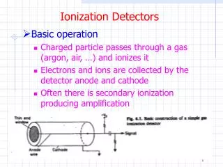
CLEO I a sparse chamber ( as seen in the event ) no local-ambiguity resolution 17 layers [ a u a v … a ] complex track overlap was a problem limited dE/dX CLEO I drift chamber 1979 – 1986 Construction: 1977-1979 D. Peterson, tracking presentation to CMS representatives 15-April-2005
CLEO II 51 layers dense cell design axial superlayers ( bushings shown in photo ) single stereo layers between the axial superlayers inner and outer cathodes ( inner shown in photo ) aluminum field wires 1.25 inch flat endplates (with 1 cm deformation) The stereo layers were difficult to calibrate; they were in a non-uniform field cage (vs Z ). CLEO II drift chamber 1986 – 1998 Construction: 1983 - 1986 D. Peterson, tracking presentation to CMS representatives 15-April-2005
CLEO III / CLEO c integrated design: space for new machine elements space for new particle ID minimal radiating material: particle ID end cap CsI calorimeter momentum resolution as good at CLEO-II - uninterrupted tracking length 0.12% X0 inner wall - improved spatial resolution cell improvements… D. Peterson, tracking presentation to CMS representatives 15-April-2005
DR 3 “wedding cake” structure; individual rings and bands The conical “big” plate deforms < 1mm. CLEO III/c drift chamber 1999 – present Design/Construction: 1992 - 1999 outer cathode D. Peterson, tracking presentation to CMS representatives 15-April-2005
ZD CLEO c inner drift chamber 2003 – present Design/Construction: 2001 - 2003 Goals: momentum resolution, sp/p, p < 1 GeV, equivalent to that of DR3 + silicon, 0.33% at 1 GeV Z0 resolution consistent with charm physics near threshold: 0.7 mm Features: very large stereo angle: d(rf)/dz = 0.1 0.01 % X0 outer wall ( 0.12 % in DR3 inner wall) provides continuous volume D. Peterson, tracking presentation to CMS representatives 15-April-2005
ZD installation an integrated assembly involving tracking and vacuum groups The interaction vacuum chamber ( 2 layer beryllium, fluid cooled ) was originally designed for installation with the clam-shelled Si-3 detector. The vacuum chamber was retrofitted into the ZD chamber retaining all cooling, radiation monitoring, and tungsten masking. A boat-in-a-bottle problem. Working with our drafting dept., down-time was reduced by 3-D modeling the installation steps. D. Peterson, tracking presentation to CMS representatives 15-April-2005
Test Chambers several test chambers; this shows two 10-layer device for measuring helium based gasses in the CLEO B-field fitted in the endcap, strapped to the final quadrupole 3:1 square and 3:1 hexagon chamber were tested 3-layer device to measure the ability to control beam backgrounds at very low radius inserted inside the, then, existing beam pipe D. Peterson, tracking presentation to CMS representatives 15-April-2005
Linear Collider TPC R&D TPC field cage, 64 cm, 20KV TPC field cage, 64 cm, 20KV TPC R&D is in collaboration with Ian Shipsey’s group at Purdue who will provide the MPGD (GEM and MicroMegas) avalanche stages. wire gas-amplification stage, readout pads field cage termination, wire grid D. Peterson, tracking presentation to CMS representatives 15-April-2005
Linear Collider TPC R&D MWPC gas-amplification single-GEM gas-amplification D. Peterson, tracking presentation to CMS representatives 15-April-2005
Track Reconstruction How to we transform the hardware signals (times and pulse heights, threshold discriminated) to a product that provides some insight into a physical process ? D. Peterson, tracking presentation to CMS representatives 15-April-2005
Pattern recognition Various methods: Some depend on intrinsic resolution, at some level requiring 3 points define circle (globally or locally). This will probably be the case for the LHC pixel detectors; layer-layer spacing >> track separation. Our current method does not depend on intrinsic resolution to seed the track. The method uses local chains of isolated hits at cell level, extends into noisier regions, then applies local-ambiguity-resolution using the precision information, extends and adds still unidentified hits, now using precision information. The algorithm has been optimized with the aid of the visual interface. D. Peterson, tracking presentation to CMS representatives 15-April-2005
Pattern recognition pathologies, some examples a) significant track overlap Loop: initiate the local-ambiguity-resolution with a range of dZ hypotheses. b) complexity in the ZD Loop: initiate the chain-finding with a range of dZ hypotheses. c) decays in flight: use tests with artificially shortened chamber radius, require decreased c2 D. Peterson, tracking presentation to CMS representatives 15-April-2005
CLEO pattern recognition, application to a Linear Collider TPC Cell count and track density are greatly increased. Cells are multi-hit; time provides the z information. At the cell level, pattern recognition is similar. Only the means of extracting precision x,y,x information is different. Scanning initial Z assumptions greatly reduces event complexity. The program structure for the scan was first developed for the TPC, then applied to the ZD scan (prev. slide). D. Peterson, tracking presentation to CMS representatives 15-April-2005
Kalman Fitting The Kalman fit compensates for energy loss degradation of information due to scattering. This is the CLEO final fit and, therefore, includes calibration, alignment, fitting weights, and hit deletion. Our implementation also provides utilities to delete non-physical hits in a neutral decay hypothesis and refit. One of the authors (Ryd) of the original CLEO II program and the sole author (Sun) of the CLEO III/c program are current members of the Cornell group. Resolution improvement: (CLEO III) Using tracks from the finder ( c2 fits in projections, corrected to vertex): Ko resolution is s~ 5 Mev. After Kalman fitter: Ko resolution is s~2 Mev. D. Peterson, tracking presentation to CMS representatives 15-April-2005
Kalman Fitting The Kalman fit is a transport method and, therefore, inherently allows application of a magnetic field map. CLEO III (c) has a 1.5 (1.0) Tesla solenoid field. The magnetic field is distorted by the fringe field of the final focus quadrupoles (slide 5) causing a 2-cycle momentum dependence. This is corrected in the Kalman fit. (The residual 1-cycle momentum dependence is due to the crossing angle) D. Peterson, tracking presentation to CMS representatives 15-April-2005
alignment many parameter problem: 2 ends - big plates, 8 small plates, ZD plates 3 variables: dx, dy, dfz start with precision optical measurements before stringing finish with clean data: Bhabha and mu pairs, cosmics. sensible constraints: optical survey, mechanical tolerances for example: big-plate-to-big-plate twist , the optical measure is superior to track measures decoupled from calibration as much as possible; use symmetric drift region. D. Peterson, tracking presentation to CMS representatives 15-April-2005
Residuals: time-measured hit position are compared to the fitted position. Parameterized as double gaussian with fixed 80% fraction in narrow component. Narrow component: s=88 mm (average over entire cell) wide component: 200 mm average : 110 mm ( Goal: 150 mm ) Calibration, Spatial Resolution Goal Narrow component of resolution w.r.t drift distance 65 mm minimum: due to calibration 135 mmat cell edge: due to cell improvements D. Peterson, tracking presentation to CMS representatives 15-April-2005
Silicon Reconstruction Issues Our experiences in track-finding and alignment have been within the context of a drift chamber tracking system. (As is the case with most groups, except for specialty VD tracking.) The track finding is aided by having closely spaced hits; this allows us to not rely on the intrinsic resolution. The silicon hit identification has been done by extrapolating the drift chamber track into the silicon. Similarly, silicon alignment was aided by using the drift chamber to define a line parallel to, but not necessarily through, the silicon hits. The all-silicon trackers* present new challenges. (* including ILC SiD ) Within a dense jet, track-finding will rely on the intrinsic resolution. But,alignment correction t intrinsic resolution . qms * extrapolation distance ?>? intrinsic resolution track separation d intrinsic resolution . Success requires (several) new approaches from several groups. A visual interface to the algorithms could expedite that success. D. Peterson, tracking presentation to CMS representatives 15-April-2005
in conclusion … We have a successful program in charged particle tracking We are involved in every aspect of tracking: hardware, commissioning, reconstruction, fitting, calibration, alignment . We approach calibrations and alignment with hardware experience. ( It is the same people.) We have implemented a visual interface to resolve pathologies in track-reconstruction, this optimizing the efficiency. We have benefited by working closely with the machine group for an integrated hardware design an understanding of backgrounds. We have extensive technical support, both with our in-house mechanical and electronics shops, and due to our experience working with outside vendors. D. Peterson, tracking presentation to CMS representatives 15-April-2005