Short Line Fault
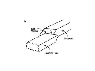
Short Line Fault. Skeats Described: L:sourc.Inductance L 1 :line Induct. To F E :Instant. emf V PW =1/2 L 1 /[L 1 + L] E 2 travel B and F At F, sh. CCT. At C.B., open CCT. . Wedge-shaped Wave Formation . Initial Distribution After Wave Separation Each reflected α C.B. Ter.=1

Short Line Fault
E N D
Presentation Transcript
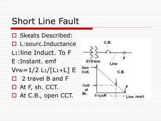
Short Line Fault • Skeats Described: • L:sourc.Inductance L1:line Induct. To F E :Instant. emf VPW=1/2 L1/[L1+L] E • 2 travel B and F • At F, sh. CCT. • At C.B., open CCT.
Wedge-shaped Wave Formation • Initial Distribution • After Wave Separation • Each reflected • α C.B. Ter.=1 • α F Ter. = -1 Voltage Distribution At different points • C.B. Ter.,middle,3/4to F
Wave Reflections • At T and 2T • How 1 and 2 reflect • At Each end V found = V1(t)+V2(t) • At C.B. start: t=0,V=Vp t=T,V=0 t=2T,V=-Vp • T; travel time to F
Wave Distribution • At C.B. Swing rate :2Vp/2T T:Very Small,atCB Fig1 Fast Rise of TRV Risk for C.B. • at Middle ----Fig2 • at ¾ to Fault--Fig3
Solution of Sh. Line Fault application of Transmission Line Response • Vs= VR Coshjω√LC+IR Z0 sinhjω√LC • Is= IR coshjω√LC+ VR/Z0 sinhjω√LC • Zs= =
Solution of Sh. Line Fault … • ZR=VR/IR • if a Sh. CCt. At Rec.ZR=0 • |Zsc|=Z0 tanh jω√LC • Substituting s for jω : • Zsc(s)=Z0 tanh√LC s • T=√LCtanhTs=sinhTs/coshTs= [1-exp(-2Ts)]/[1+exp(-2Ts)] • exp(-2Ts)=α tanh Ts=(1-2α+2α^2- 2α^3+..) • Z(s)=Z0 [1-2exp(-2Ts)+2exp(-4Ts)-2…]
Recovery Voltage Determination • Injecting minus fault current into CCT • I=-E/[L+L1] . T • i(s)=-E/[L+L1] . 1/s • response of Sh. Trans. Line : i(s)Z(s)=-E/[L+L1] Z0 1/s[1-2e^(-2Ts) +2e^(-4Ts)-…] • Inverse Transform results in TRV • 1st neg. ramp slope Z0 X current • Next terms ramp 2xslope of 1st delayed: 2T,4T,6T,… and alternate in Sign Sum a Saw tooth wave ∆t=4T, Vpp=E/[L+L1] Z0 2T Z0T=L1 Vpp=2EL1/[L+L1]
CCT TRV • Response of shorted line Calculated • Response of source side: If source : by parallel L & C Rise a TRV of 1–cosine form T=2Π√LC & Amplitude EL/[L+L1] ,i.e.: Vsource =E L/[L+L1] {1-cos t/√LC} • VC.B.=Vsource-Vshort fault as in Figure
Transformer Transient Model • Have the greatest exposure to electrical Transients (after Transmission line) • Different Model for specific studies • Transformer Model for: Switching on OPEN CCT • Im & Ih+e so a parallel RL CCT, & Cg capacitance of winding with length l R0=V/W0 • Cg/l per unit length & small fraction (Cg/l)∆x
Transformer Equivalent CCT • As a load on Auto Transformer • Its Imp.:l/[ωCg∆x] • looking to A seen As : (l/x){l/[ωCg∆x]} • Related Cap.: Cg x ∆x /l • Ceff=Cg/l∫xdx • Integrating 0 to l Ceff=Cg/l[x/3]=Cg/3
Other Models • Terminal Model & Detailed Model 1- Based on Name plate Information A paper, not discussed here 2-Software for Transformer Transient Study , not discussed here • Internal Model for a Transformer for special studies
Internal Model • for our purpose Detailed one not desirable • Divide the time after surge into: 1- extremely short (about fraction of μs) 2- Next in range of m S and seconds 3- the steady state • In the fraction of μs no current penetrate to inductance only displacements currents to Capacitances
Initial Distribution • Eq. CCT. • Cg:Cap to Gr Cs:Cap from end to end of winding • Gr Cap./unit length=Cg/l SeriesCap./length=Cs l E:voltage at any point on winding Ig=total current in Gr Cap Is=current in series Cap
Elementary length of Winding • The Gr current: ∆Ig=Cg ∆x ωE/l (1) • Also : ∆Ig=dIs/dx ∆x (2) • With (1) & (2): dIs/dx=CgωE/l (3) • Series Cap. Of Elem. Length: l Cs/∆x
Deriving Eeuations • Voltage across Element=dE/dx ∆x • series Cap. current=C dE/dt • Is=l Csω dE/dx (4) • Differentiating above Eq. : dIs/dx=lCsω dE/dx (5) Equate (3) & (5): dE/dx-1/l Cg/CsE=0 (6)
Fast Response of winding to switching • The General solution of Eq.(6): E=A1 e^px + A2 e^-px • where p=1/l √Cg/Cs • A1& A2 from Boundary Conditions • NEUTRAL GROUNDED: x=0, E=0 and x=l, E=V • V amplitude of step surge
Coefficients for Neutral Gr • A1+A2=0, A1e^pl+A2e^-pl=V A1=-A2=V/[ e^pl- e^-pl ] • If pl=√Cg/Cs=α • A1=-A2=V/[2sinhα] • E=V/[2sinhα] . {e^px – e^-px}= = V sinh(αx/l)/sinhα (7) • If Neutral Isolated: x=l , E=V & x=0 , Is=0 or dE/dx=0
Coefficient of Neutral Isolated • Two Boundary Eqs: p(A1-A2)=0 A1e^pl + A2e^-pl=V • Coefficients are : A1=A2=V/[2cosh pl]=V/[2coshα] • The response : • E= V/2coshα [e^px + e^-px]= V cosh(αx/l) / coshα (8) Eqs (7) & (8) are Initial Voltage Distribution
Discussion on responses • both depend on α=√Cg/Cs • More Nonuniform as α increases • α=10% to 60% voltage across the 1st 10% of winding at Line end • The Gradient at line terminal by differentiating: • a- Gr Neutral dE/dx=α/l V cosh(αx/l)/ sinhα; x=l dE/dx=αV/l cothα • B-Neutral Isolated dE/dx=α/l V sinh(αx/l)/coshα x=l dE/dx= αV/l tanhα
Discussion Continued • For large values of α, cothα=tanhα=1 ; dE/dx=αV/l or is α times mean Gradient • Under Surge; Turns Insulation at Line End Severly Stressed • Slower fronted surges, capacitance not governing Voltage distribution • Winding Cap.:Geometery Dependent
Discussion Continued • Different Winding Styles : Vary in α • Source of steep fronted surges: Flashover of an insulator, closing of a switch or C.B.,reignition in a switch,Fast Trans. in opening GISswitches,Lightning • Remedial Methods: strengthen End turn insulation; Failed placing metallic shields, Design interleaved Winding
Initial and Approximate limit of Excursion • Ceff of a winding, excited by V at ω • I=ωCeffV , Is=ωCsl dE/dx [Is]l=ωCsl (dE/dx)l; (dE/dx)l=α(V/l) cothα • Thus: ωCeffV=ωCsαV cothα or : Ceff=αVscothα=√Cg/Cs Cs cothα • Typical α, cothα=1, therefore:Ceff=√CgCs
A sample Transformer • Cg=3000 PF, Cs=30 PF • α=√3000/30=10 Ceff=√90000=300PF • For a Transmission Line Z0=400Ω charging Time const.=400x3x 10^-10=0.12μs • Points with transients: starts at initials, and finally Osc. About some Final value: Swing almost as far above steady value as starts below it In winding Final Dis. Uniform or it is the α=0 line Therefore excursions of any point lie within the envelope
Lightning • Lightning greatest cause of outages: 1- 26% outages in 230 KV CCTs & 65% of outages in 345 KV Results of study on 42 Companies in USA & CANADA • And 47% of 33 KV sys in UK study of 50000 faults reports Also Caused by Lightning • Clouds acquire charge& Electric fields within them and between them
Development • When E excessive:space Insulation Breakdown or lightning flash occur • A high current discharge • Those terminate on or near power lines • similar to:close a switch between cloud & line or adjacent earth • a direct con. Or through mutual coupling
Lightning surge • Disturbance on a lineTraveling wave • Travel both Direction, 1/2IZ0 I: lightning current Z0=Surge Imp. Line • The earth carries a net negatve charge of 5x10^5 C, downward E=0.13KV/m • An equivalent pos. charge in space • Upper Atmosph. Mean potential of 300 KV relative to earth
Lightning • Localized charge of thunder clouds superimposes its field on the fine weather field, freq. causing it to reverse • As charges within cloud & by induction on earth below, field sufficient Breakdown(30 KV/cm) • Photographic evidence:a stepped leader stroke, random manner &short steps from cloud to earth • Then a power return stroke moves up the ionized channel prepared by leader
Assignment N0.4 (Solution) • Question 1 • 13.8 KV, 3ph Bus L=0.4/314=1.3 mH Xc=13.8/5.4=35.27 Ω, C=90.2μF • Z0=10√1.3/9.02=3.796Ω • Vc(0)=11.27KV • Ipeak=18000/3.796= 4.74 KA
Question 1 • 1- Vp=2x18-11.27=24.73 KV Trap • 2- Assuming no damping, reaches Again the same neg. peak and 11.27KV trap • 3- 1/2 cycle later –(18-11.27)=-6.73 Vp2=-(24.73+2x6.73)=-38.19 KV
Question 2 • C.B. reignites during opening&1st • Peak voltage on L2 L2=352,L1=15mH, C=3.2nF So reigniting at Vp, 2 comp.: • Ramp:Vs(0).t/[L1+L2]= 138√2x10/[√3(352+15)x10-]=0.307x10^6 t • Oscill.of : f01=1/2Π x {√[L1+L2]/L1L2C} • Z0=√{L1L2/[c(L1+L2)]} • component2:as Sw closes Ic=[Vs(0)-Vc(0)] /√{L1L2/[c(L1+L2)]} ≈2Vp√C/L1=104.1 A
Question 2 continued • Eq of Reignition current I’ t + Im sinω0t which at current zero: sinω0t=-I’t/Im , ω0=1/√LC1=1.443x10^5 • Sin 1.443x10^5t=-0.307x10^6t/104.1=-2.949x10^3t • Sin 1.443x10^5t =-2.949x10^3t t(μs): 70 68 67 66.7 66.8 -0.6259 -0.3780 -0.2409 -0.1987 -0.1959 -0.2064 0.2005 -0.1376 -0.1967 -0.1966
Question 2 • t=66.68μs I1=0.307x66.68=20.47 A • Vp=I1√L2/C=20.47x10.488=214.7 KV
Question 3 • 69 KV, 3ph Cap. N isolated, poles interrupt N.Seq. • 160◦ 1st reignite • Xc=69/30=158.7 C=20μF,CN=0.02μF Vs-at-reig=69√2/3cos160 =-52.94 KV • Trap Vol.: • V’A(0)=56.34KV V’B(0)=20.62KV,V’C(0)= -76.96KV,VCN(0)=28.17KV • Vrest=56.34+28.17+52.94=137.45 KV
Question 3 continued • Z0=√L/CN=√5.3x0.2 x100=514Ω • Ip-restrike=137.45/514=0.267KA=267A • F0=1/[2Π√LCN]=10^6/{2Π√53x2}=15.45 KHz • Voltage swing N=2x137.45=274.9 KV • VN=28.7-274.9=-246.73 KV • VB’=-246.73+20.6=-226.13 KV • VC’=-246.73+-76.96=-323.69 KV