Overview of Link Layer Functionality and Internet Routing Principles
This assignment covers key concepts of the Link Layer and how they relate to internet routing. Topics include intradomain and interdomain routing, Classless Inter-Domain Routing (CIDR) for address aggregation, and long-prefix matching for determining next hops. We discuss examples of frame encapsulation and data encapsulation from one node to another, as well as address resolution using ARP. Your feedback on the course would be greatly appreciated, and replacement work discussions are welcome. Course slides will be provided for further reading over the summer.

Overview of Link Layer Functionality and Internet Routing Principles
E N D
Presentation Transcript
Link Layer 4/19/2012
Admin • Written Assignment—Network new due date: Monday, April 23 • If you are considering replacement work, please stop by to talk to me • Any feedback/suggestions on the course will be appreciated.
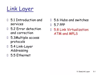
Recap: Internet Routing • Intradomain routing and interdomain routing • CIDR to allow flexibility in aggregation of destination addresses to improve routing scalability • Longest prefix matching to determine the next hop to a destination • Basic switching fabric design
forwarding table in A Dest. Net. next router Nhops B A 223.1.1/24 1 223.1.2/24 223.1.1.4 2 223.1.3/24 223.1.1.4 2 0.0.0.0/0 223.1.1.4 - Putting it Together: Example 1 (same network): A->B src dst misc fields data 223.1.1.1 223.1.1.3 • Look up dest address • find dest is on same net • Hand datagram to link layer to send inside a link-layer frame To Internet 223.1.1.1 223.1.4.1 223.1.2.1 223.1.1.2 223.1.2.9 223.1.1.4 223.1.2.2 223.1.1.3 223.1.3.27 223.1.3.2 223.1.3.1
forwarding table in A Dest. Net. next router Nhops B A E 223.1.1/24 1 223.1.2/24 223.1.1.4 2 223.1.3/24 223.1.1.4 2 223.1.1.1 223.1.2.1 223.1.1.2 223.1.2.9 223.1.1.4 223.1.2.3 223.1.1.3 223.1.3.27 223.1.3.2 223.1.3.1 Putting it Together: Example 2 (Different Networks): A-> E misc fields data 223.1.1.1 223.1.2.3 • look up dest address in forwarding table • routing table: next hop router to dest is 223.1.1.4 • Hand datagram to link layer to send to router 223.1.1.4 inside a link-layer frame • the dest. of the link layer frame is 223.1.1.4 0.0.0.0/0 223.1.1.4 - To Internet 223.1.4.1
Summary of Network Layer • We have covered the basics of the network layer • routing and forwarding • There are multiple other topics that we did not cover • Multicast/anycast • QoS • slides will be linked on the schedule page just in case you need reading in the summer
Recap: The Hourglass Architecture of the Internet Telnet Email FTP WWW TCP UDP IP Ethernet Wireless FDDI CableDOCSIS ADSL
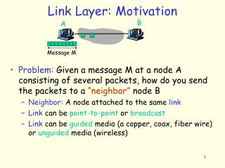
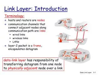
Link Layer: Introduction “link” Some terminology: • hosts and routers are nodes (bridges and switches too) • communication channels that connect adjacent nodes along a communication path are links • wired, wireless • dedicated, shared • 2-PDU is called a frame,encapsulates 3-PDU datagram
Link layer: Context • Data-link layer has responsibility of transferring datagram from one node to another node • Datagram may be transferred by different link protocols over different links, e.g., • Ethernet on first link, • frame relay on intermediate links • 802.11 on last link transportation analogy • trip from New Haven to San Francisco • taxi: home to union station • train: union station to JFK • plane: JFK to San Francisco airport • shuttle: airport to hotel
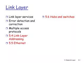
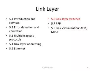
Link Layer Services • Framing • encapsulate datagram into frame, adding header, trailer and error detection/correction • Multiplexing/demultiplexing • frame headers to identify src, dest • Media access control • Forwarding/switching with a link-layer (Layer 2) domain • Reliable delivery between adjacent nodes • we learned how to do this already ! • seldom used on low bit error link (fiber, some twisted pair) • common for wireless links: high error rates
frame frame Adaptors Communicating datagram receiving node link layer protocol sending node adapter adapter • sending side: • encapsulates datagram in a frame • adds error checking bits, rdt, flow control, etc. • receiving side • looks for errors, rdt, flow control, etc • extracts datagram, passes to receiving node • link layer typically implemented in “adaptor” (aka NIC) • Ethernet card, modem, 802.11 card • adapter is semi-autonomous, implementing link & physical layers
LAN/MAC/Physical Address • In most link-layer, each adapter has a unique link layer address (also called MAC address) • used as address in datalink frames to identify the interface • 48 bit MAC address (for most types of LANs) burned in the adapter ROM • MAC address allocation administered by IEEE; • manufacturer buys portion of MAC address space (to assure uniqueness)
223.1.1.1 E B A C 223.1.2.1 223.1.1.2 223.1.2.9 223.1.1.4 223.1.2.2 223.1.3.27 223.1.1.3 223.1.3.2 223.1.3.1 frame source, dest address datagram source, dest address Question: how to determine MAC address of C knowing C’s IP address? A’s IP addr E’s IP addr C’s MAC addr A’s MAC addr IP payload datagram frame Recall Earlier Routing Discussion Starting at A, given IP datagram addressed to E: • look up net. address of E, find C • link layer sends datagram to C inside link-layer frame; the dest. address should be C’s MAC address
ARP: Address Resolution Protocol • Each IP node (Host, Router) on LAN has ARP table • ARP Table: IP/MAC address mappings for some LAN nodes < IP address; MAC address; TTL> • TTL (Time To Live): time after which address mapping will be forgotten (typically 20 min) [yry3@cicada yry3]$ /sbin/arp Address HWtype HWaddress Flags Mask Iface zoo-gatew.cs.yale.edu ether AA:00:04:00:20:D4 C eth0 artemis.zoo.cs.yale.edu ether 00:06:5B:3F:6E:21 C eth0 lab.zoo.cs.yale.edu ether 00:B0:D0:F3:C7:A5 C eth0
ARP is “plug-and-play”: nodes create their ARP tables without intervention from net administrator A broadcast protocol: source broadcasts query frame, containing queried IP address all machines on LAN receive ARP query destination D receives ARP frame, replies frame sent to A’s MAC address (unicast) ARP Protocol
IP address is locator address depends on network to which an interface is attached NOT portable introduces features (e.g., CIDR) for routing scalability IP address needs to be globally unique (if no NAT) Comparison of IP address and MAC Address • MAC address is an identifier • dedicated to a device • portable • flat • MAC address does not need to be globally unique, but the current assignment ensures uniqueness
Outline • Admin • Link layer overview • Error detection
Error Detection • D = Data protected by error checking, may include header fields • ED = Error Detection bits (redundancy) • Error detection not 100% reliable! • a good error detector may miss some errors, but rarely • larger ED field generally yields better detection • Error detection design considers computation primitives.
Cyclic Redundancy Check: Background • Widely used in practice, e.g., • Ethernet, DOCSIS (Cable Modem), FDDI, PKZIP, WinZip, PNG • For a given data D, consider it as a polynomial D(x) • consider the string of 0 and 1 as the coefficients of a polynomial • e.g. consider string 10011 as x4+x+1 • addition and subtraction are modular 2, thus the same as xor • Choose generator polynomial G(x) with r+1 bits, where r is called the degree of G(x)
x + Cyclic Redundancy Check: Encode • Given data G(x) and D(x), choose R(x) with r bits, such that • D(x)xr+R(x) is exactly divisible by G(x) • The bits correspond to D(x)xr+R(x) are sent to the receiver
8 6 6 2 4 46-1500 (including padding) Ethernet Frame Structure Sending adapter encapsulates IP datagram (or other network layer protocol packet) in Ethernet frame • Preamble: 8 bytes • 7 bytes with pattern 10101010 followed by one byte with pattern 10101011 (why the preamble?) • Source and dest. addresses: 6 bytes • Type: indicates the higher layer protocol, mostly IP but others may be supported such as Novell IPX and AppleTalk • CRC: CRC-32 checked at receiver, if error is detected, the frame is simply dropped
Cyclic Redundancy Check: Decode • Since G(x) is global, when the receiver receives the transmission T’(x), it divides T’(x) by G(x) • if non-zero remainder: error detected! • if zero remainder, assumes no error T’ T = D(x)xr+R(x) Encode:CRC(G) check D
CRC: Steps and an Example Suppose the degree of G(x) is r Append r zero to D(x), i.e. consider D(x)xr Divide D(x)xr by G(x). Let R(x) denote the reminder Send <D, R> to the receiver
The Power of CRC • Let T(x) denote D(x)xr+R(x), and E(x) the polynomial of the error bits • the received signal is T’(x) = T(x)+E(x) • Since T(x) is divisible by G(x), we only need to consider if E(x) is divisible by G(x) T’ T = D(x)xr+R(x) Encode:CRC(G) check D
Designing CRC • Detect a single-bit error: E(x) = xi • if G(x) contains two or more terms, E(x) is not divisible by G(x) • Detect an odd number of errors: E(x) has an odd number of terms: • lemma: if E(x) has an odd number of terms, E(x) cannot be divisible by (x+1) • suppose E(x) = (x+1)F(x), let x=1, the left hand will be 1, while the right hand will be 0 • thus if G(x) contains x+1 as a factor, E(x) will not be divided by G(x) • Many more errors can be detected by designing the right G(x)
Example G(x) • 32 bits CRC: • CRC32: x32 + x26 + x23 + x22 + x16 + x12 + x11 + x10 + x8 + x7 + x5 + x4 + x2 + x + 1 • used by Ethernet, FDDI, PKZIP, WinZip, and PNG • GSM phones • For more details see the link below and further links it contains: • http://en.wikipedia.org/wiki/Cyclic_redundancy_check .
Outline • Admin • Link layer overview • Error detection/correction • Link access
Multiple Access Links and Protocols Two types of “links”: • point-to-point • e.g., a leased dedicated line, PPP for dial-up access • broadcast (shared wire or medium) • traditional Ethernet; Cable networks • 802.11 wireless LAN; cellular networks • satellite
Multiple Access Protocols • Single shared broadcast channel • thus, if two or more simultaneous transmissions by nodes, due to interference, only one node can send successfully at a time (see CDMA later for an exception) multiple access protocol • Protocol that determines how nodes share channel, i.e., determines when nodes can transmit • Communication about channel sharing must use channel itself ! • Discussion: properties of an ideal multiple access protocol.
Ideal Mulitple Access Protocol Broadcast channel of rate R bps • Efficiency: when only one node wants to transmit, it can send at full rate R • Rate allocation: • simple fairness: when N nodes want to transmit, each can send at average rate R/N • we may need more complex rate control • Decentralized: • no special node to coordinate transmissions • no synchronization of clocks • Simple
MAC Protocols: a Taxonomy Goals • efficient, rate control, decentralized, simple Three broad classes: • channel partitioning • divide channel into smaller “pieces” (time slot, frequency, code) • non-partitioning • random access • allow collisions • “taking-turns” • a token coordinates shared access to avoid collisions
Outline • Admin. and recap • Link layer overview • Error detection and correction • Media access control (MAC) protocols • channel partitioning
Channel Partitioning: TDMA TDMA: time division multiple access • Access to channel in "rounds" • Each station gets fixed length slot (length = pkt trans time) in each round • Unused slots go idle • Example: 6-station LAN, 1,3,4 have pkt, slots 2,5,6 idle
Channel Partitioning: FDMA FDMA: frequency division multiple access • Channel spectrum divided into frequency bands • Each station assigned fixed frequency band • Unused transmission time in frequency bands go idle • Example: 6-station LAN, 1,3,4 have pkt, frequency bands 2,5,6 idle time 1 2 3 frequency bands 4 5 6
5 7 8 1 2 4 6 3 4.615 ms 546.5 µs 577 µs GSM - TDMA/FDMA 935-960 MHz 124 channels (200 kHz) downlink frequency 890-915 MHz 124 channels (200 kHz) uplink time GSM TDMA frame GSM time-slot (normal burst) guard space guard space S user data tail tail user data S Training 1 3 1 57 bits 3 bits 57 bits 26 bits S: indicates data or control
Channel Partitioning: CDMA CDMA (Code Division Multiple Access) • Used mostly in wireless broadcast channels (cellular, satellite, etc) • A spread-spectrum technique History: http://people.seas.harvard.edu/~jones/cscie129/nu_lectures/lecture7/hedy/lemarr.htm
CDMA: Encoding • All users share same frequency, but each user m has its own unique “chipping” sequence (i.e., code) cm to encode data, i.e., code set partitioning • e.g. cm = 1 1 1 -1 1 -1 -1 -1 • Assume original data are represented by 1 and -1 • Encoded signal = (original data) modulated by (chipping sequence) • assume cm = 1 1 1 -1 1 -1 -1 -1 • if data is d, send d cm, • if data d is 1, send cm • if data d is -1 send -cm
CDMA: Encoding tb user data d(t) 1 -1 X tc chipping sequence c(t) -1 1 1 -1 1 -1 1 -1 1 1 -1 1 -1 1 = resulting signal -1 1 1 -1 1 -1 1 1 -1 -1 1 -1 1 -1 tb: bit period tc: chip period
CDMA: Decoding • Inner-product (summation of bit-by-bit product) of encoded signal and chipping sequence • if inner-product > 0, the data is 1; else -1
CDMA Encode/Decode Encode Code of user m cm: 1 1 1 -1 1 -1 -1 -1 Decode • The number of bitsof each chipping sequence is M
CDMA: Deal with Multiple-User Interference • Two codes Ci and Cj are orthogonal, if • , where we use “.” to denote inner product, e.g. • If codes are orthogonal, multiple users can “coexist” and transmit simultaneously with minimal interference: C1: 1 1 1 -1 1 -1 -1 -1 C2: 1 -1 1 1 1 -1 1 1 ----------------------------------------- C1 . C2 = 1 +(-1) + 1 + (-1) +1 + 1+ (-1)+(-1)=0 Analogy: Speak in different languages!
CDMA: Two-Sender Interference Code 1: 1 1 1 -1 1 -1 -1 -1 Code 2: 1 -1 1 1 1 -1 1 1
Discussions • Advantages of channel partitioning • Problems of channel partitioning
Outline Recap Link layer overview Error detection and correction MAC protocols Partitioning protocols Non-partitioning MAC protocols Random access 44
Random Access Protocols • When a node has packets to send • transmit at full channel data rate R • no a priori coordination among nodes • Two or more transmitting nodes -> “collision” • Random access MAC protocol specifies: • when to access channel? • how to detect collisions? • how to recover from collisions? • Examples of random access MAC protocols: • slotted ALOHA and pure ALOHA • CSMA and CSMA/CD, CSMA/CA
Slotted Aloha [Norm Abramson] • Time is divided into equal size slots (= pkt trans. time) • Node with new arriving pkt: transmit at beginning of next slot • If collision: retransmit pkt in future slots with probability p, until successful. Success (S), Collision (C), Empty (E) slots
Slotted Aloha Efficiency Q: What is the fraction of successful slots? suppose n stations have packets to send suppose each transmits in a slot with probability p - prob. of succ. by a specific node: p (1-p)(n-1) - prob. of succ. by any one of the N nodes S(p) = n * Prob (only one transmits) = n p (1-p)(n-1)
Slotted Aloha Goodput vs. Offered Load S = throughput = “goodput” (success rate) 1.5 2.0 0.5 1.0 G = offered load = np • when p n < 1, as p (or n) increases • probability of empty slots reduces • probability of collision is still low, thus goodput increases • when p n > 1, as p (or n) increases, • probability of empty slots does not reduce much, but • probability of collision increases, thus goodput decreases • goodput is optimal when p n = 1
At best: channel use for useful transmissions 37% of time! Maximum Efficiency vs. n 1/e = 0.37
Pure (unslotted) Aloha • Unslotted Aloha: simpler, no clock synchronization • Whenever pkt needs transmission: • send without awaiting for the beginning of slot • Collision probability increases: • pkt sent at t0 collide with other pkts sent in [t0-1, t0+1]