Download

1 / 44
450 likes | 741 Vues
CubeSat Design for Solar Sail Testing Applications. Phillip Hempel Paul Mears Daniel Parcher Taffy Tingley. The University of Texas at Austin. October 11, 2001. Presentation Outline. Project Goal. Management Structure. Satellite Systems. Budget. Future Work. Conclusion. Project Goal.

E N D
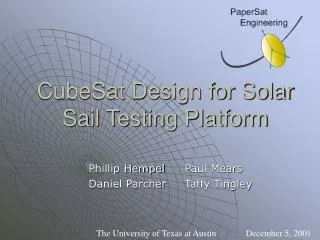
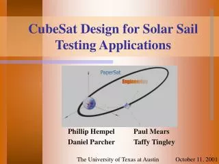
CubeSat Design for Solar Sail Testing Applications Phillip Hempel Paul Mears Daniel Parcher Taffy Tingley The University of Texas at Austin October 11, 2001
Presentation Outline Project Goal Management Structure Satellite Systems Budget Future Work Conclusion
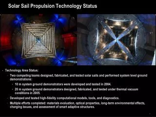
Project Goal • Design a Test Platform for Solar Sail Propulsion Technology • Measure Thrust • Measure Solar Sail Efficiency
Management Structure • Daniel Parcher • Project Manager • Tracking Systems Department Head • Electronics Department Head • Phillip Hempel • Mechanical Systems Department Head • Taffy Tingley • Propulsion Systems Department Head • Paul Mears • Orbital Trajectory Department Head
CubeSat Project Background • Sponsored by Stanford University • Utilizes picosatellite satellite Designs that perform some scientific task • Different CubeSat launches provide different initial conditions
Constraints • CubeSat Prescribed Constraints • 10cm Sided Cube • 1 Kg Weight • Timing System to Delay Power-On • Space-Flown Materials • Adopted Constraints (for Simplicity and Reliability) • No Attitude Control • No Powered Systems (except required Timer) • No Communications Systems
Presentation Outline Project Overview Management Structure Satellite Systems Budget Future Work Conclusion
CubeSat Required Systems • Timer • RDAS accelerometer/timer • Voltage outputs to trigger system events • Casing • Aluminum • Kill Switch • Attached CC reflectors
Tracking / Communcations • No Satellite Communication • Tracking performed with corner cube reflectors • determine position, rotation, acceleration • Corner cube reflectors to be supplied by Banner Engineering Corp.
Mechanical Systems Phillip Hempel
Satellite Components • Frame/ Corner Cube Reflectors • Kill Switch/ Timer • Sail • Inflation Capsule • Capillaries • Hardening Strips
Frame • 10 cm Sided Cube • Corner Cubes Panels to be Placed on Sides
Corner Cube Reflectors • Flat-Plate Reflectors • Attached to Frame • Released Prior to Inflation • In the Plane of the Solar Sail
Kill Switch/Timer • Kill Switch Triggered by Release • Begins Timer Sequence • Controls All Timing Sequences
Solar Sail Properties • Aluminized Mylar • Circular Shape • Area of 100 m^2 Example of Aluminized Mylar Structure
Capillaries • Tubes attached to the surface of the solar sail • Capillaries will be placed placed strategically for structural rigidity • Tubes are inflated by nitrogen from capsule Total Length = 272 ft. Diameter = 0.5 in
Inflation Capsule • 7.6 cm Long • 3.8 cm Diameter • 86 cm^3 Volume • 60.5 psi • Placed in the Center of the CubeSat
Hardening Strips • Thin tape-like strips • Strips will be placed strategically in a spider web pattern on the sail • Strips harden with solar radiation exposure Total Strip Length = 308 ft.
Sequence of Events • P-Pod Release/ Deactivate Kill Switch • Waiting Period • Side Panels Unlock • Inflation Begins • Inflation Ends/ Rigidization Occurs • Solar sail reaches final shape
Propulsion Taffy Tingley
Solar Sail Material Selection Solar Blade Solar Sail Encounter Satellite
Solar Sail Material Selection Cosmos I Star of Tolerance Satellite
Aluminized Mylar • High Strength to Weight Ratio • Tested • Cheap! • Double Reflective
Finite Element Design • Monitor regions where high stress occurs • Add tear strip or tension line to sail • Monitor rigidity • Model several perturbations and situations • Perform thermal analysis • Monitor effects of additional components • All in 3-D
Future Propulsion Work • Integrate deployment apparatus into FE model • Install Tear Strips into FE model • Perform Thermal Analysis
Orbit Simulation Paul Mears
Solar Radiation Pressure • Electromagnetic radiation flux • Photon energy • Momentum exchange produces force per unit area ΔV
Sail Thrust Function of: T = f (A, S, e, q) where A = sail area S = Power (scaled Watt) e = reflectivity q = angle of incidence
-Fr Fi θ FT Fr ŜN Sail Thrust Vector • Thrust Acts in the direction Normal to the Sail • Sail Normal makes an angle q with the Sun Position Vector • Thrust is generated by Incidental and Reflected Light
4-Body Problem ECEF Coordinate System (x, y, z) • Earth (2) Sun (3) Moon • (4) Satellite (T) Thrust
Forces on the Satellite The gravitational forces of all the planets effect the satellite, as well as thrust FBD: Satellite i = 1, 2, 3
Injection will occur at perigee Orbit will be highly elliptic with apogee at 42000km Resulting Orbital Elements Rp = 7178.14 km Ra = 48619.23 km Vp = 10.19 km/s2 Va = 3.04 km/s2 e = 0.743 a = 55797.37 km Initial Conditions of Orbit
Orbit Propagation: Perturbing Forces Earth Forces Only Earth, Sun, Moon Forces
Orbit Propagation with Thrust All Gravitational Forces plus Thrust Earth, Sun, Moon Forces
Future Work in Orbit Simulation Rotating Thrust Vector
Presentation Outline Project Overview Management Structure Satellite Systems Budget Future Work Conclusion
Budget • Personnel - $15,633 • Testing - $ 2,000 • Materials - $ 5,000 • Launch - $50,000 • Total - $72,653
Future Work • Hardware integration • Part size and weight definition and orientation within the satellite • Deployment system timing • Finite element analysis • Orbital simulation • Rotating thrust vector definition • Orbital trajectories simulation
Conclusion • PaperSat is developing a picosatellite design for CubeSat • Design will test solar sail propulsion technology • Design will not incorporate attitude control • Deployment system uses compressed gas • Solar sail will be reflective on both sides • Position, acceleration, and orientation will be measured from ground stations http://www.ae.utexas.edu/design/papersat/
Acknowledgements • Dr. Wallace Fowler • Dr. Cesar Ocampo • Dr. Eric Becker • Meredith Fitzpatrick • Previous CubeSat Design Groups