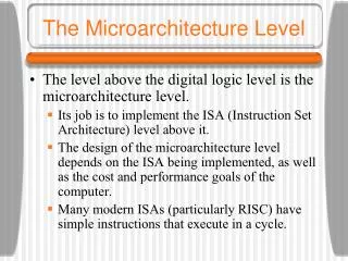
The Microarchitecture Level
The Microarchitecture Level. Chapter 4. Core i7’s Sandy Bridge Microarchitecture. The decoded micro-ops are fed into the micro-op cache, which Intel refers to as the L0 (level 0) instruction cache.


The Microarchitecture Level
E N D
Presentation Transcript
The Microarchitecture Level Chapter 4
Core i7’s Sandy Bridge Microarchitecture • The decoded micro-ops are fed into the micro-op cache, which Intel refers to as the L0 (level 0) instruction cache. • The micro-op cache is similar to a traditional instruction cache, but it has a lot of extra breathing room to store the micro-op sequences that individual instructions produce. • When the decoded micro-ops rather than the original instructions are cached, there is no need to decode the instruction on subsequent executions. • This speeds up the pipeline, but Intel claims that the micro-op cache was added to reduce front end power consumption. • With the micro-op cache in place, the remainder of the front end sleeps in an unclocked low-power mode 80% of the time.
Core i7’s Sandy Bridge Microarchitecture • Branch prediction is also performed in the front end. • The branch predictor is responsible for guessing when the program flow breaks from pure sequential fetching • The branch predictor in the Core i7 is quite remarkable but the specifics are closely held secrets for most designs. • Instructions are fed from the micro-op cache to the out-of-order scheduler in the order dictated by the program, but they are not necessarily issued in program order. • When a micro-op that cannot be executed is encountered, the scheduler holds it but continues processing the instruction stream to issue subsequent instructions all of whose resources (registers, functional units, etc.) are available. • Register renaming is also done here to allow instructions with a WAR or WAW dependence to continue without delay.
Core i7’s Sandy Bridge Microarchitecture • Although instructions can be issued out of order, the Core i7 architecture’s requirement of precise interrupts means that the ISA instructions must be retired in original program order. • The retirement unit handles this chore. • In the back end of the processor we have the execution units, which carry out the integer, floating-point, and specialized instructions. • Multiple execution units exist and run in parallel. • They get their data from the register file and the L1 data cache.
Core i7’s Sandy Bridge Pipeline (1) Figure 4-47. A simplified view of the Core i7 data path.
Core i7’s Sandy Bridge Pipeline (2) • The front end is fed new x86 instructions from the L1 instruction cache. • It decodes them into micro-ops for storage in the micro-op cache, which holds approximately 1.5K micro-ops. • A micro-op cache of this size performs comparably to a 6-KB conventional L0 cache. • The micro-op cache holds groups of six micro-ops in a single trace line. • For longer sequences of micro-ops, multiple trace lines can be linked together. • If the decode unit hits a conditional branch, it looks up its predicted direction in the Branch Predictor. • The branch predictor contains the history of branches encountered in the past; it uses this history to guess future conditional branches
Core i7’s Sandy Bridge Pipeline (2) • If the branch instruction is not in the table, static prediction is used. • A backward branch (part of a loop) and assumed to be taken. • The accuracy of these static predictions is extremely high. • A forward branch (part of an if statement) and is assumed not to be taken. • The accuracy of these static predictions is much lower than that of the backward branches. • For a taken branch the BTB (Branch Target Buffer) is consulted to determine the target address. • The BTB holds the target address of the branch the last time it was taken. • Indirect branches (C++ switch statements), go to many addresses, and they may be mispredicted by the BTB.
Core i7’s Sandy Bridge Pipeline (2) • The second part of the pipeline, the out-of-order control logic, is fed from the micro-op cache. • As each micro-op comes in from the front end, up to four per cycle, the allocation/renaming unit logs it in a 168-entry table called the ROB (ReOrder Buffer). • This entry keeps track of the status of the micro-op until it is retired. • The allocation/renaming unit then checks to see if the resources the micro-op needs are available. • If so, the micro-op is enqueued for execution in one of the scheduler queues. • Separate queues are maintained for memory and nonmemory micro-ops.
Core i7’s Sandy Bridge Pipeline (2) • If a micro-op cannot be executed, it is delayed, but subsequent micro-ops are processed, leading to out-of-order execution of the micro-ops. • This strategy was designed to keep all the functional units as busy as possible. • As many as 154 instructions can be in flight at any instant, and up to 64 of these can be loads from memory and up to 36 can be stores into memory. • Sometimes a micro-op stalls because it needs to write into a register that is being read or written by a previous micro-op. • These conflicts are called WAR and WAW dependences. • By renaming the target of the new micro-op to allow it to write its result in one of the 160 scratch registers, it may be possible to schedule the micro-op for execution immediately.
Core i7’s Sandy Bridge Pipeline (2) • If no scratch register is available, or the micro-op has a RAW dependence, the allocator notes the nature of the problem in the ROB entry. • When all the required resources become available later, the micro-op is put into one of the scheduler queues. • The scheduler queues send micro-ops into the six functional units (as under) when they are ready to execute. • ALU 1 and the floating-point multiply unit. • ALU 2 and the floating-point add/subtract unit. • ALU 3 and branch processing and floating-point comparisons unit. • Store instructions. • Load instructions 1. • Load instructions 2.
Core i7’s Sandy Bridge Pipeline (2) • Since the schedulers and the ALUs can process one operation per cycle, a 3-GHz Core i7 has the scheduler performance to issue 18 billion operations per second; • however, in reality the processor will never reach this level of throughput. • Since the front end supplies at most four micro-ops per cycle, six micro-ops can only be issued in short bursts since soon the scheduler queues will empty. • Also, the memory units each take four cycles to process their operations, thus they could contribute to the peak execution throughput only in small bursts. • Despite not being able to fully saturate the execution resources, the functional units do provide a significant execution capability, and that is why the out-of-order control goes to so much trouble to find work for them to do.
Core i7’s Sandy Bridge Pipeline (2) • The ALU and floating-point units are fed by a pair of 128-entry register files, one for integers and one for floating-point numbers. • The Sandy Bridge architecture introduced the Advanced Vector Extensions (AVX), which supports 128-bit data-parallel vector operations. • The vector operations include both floating-point and integer vectors, and this new ISA extension represents a two-times increase in the size of vectors now supported compared to the previous SSE and SSE2 ISA extensions. • How does the architecture implement 256-bit operations with only 128-bit data paths and functional units? • It cleverly coordinates two 128-bit scheduler ports to produce a single 256-bit functional unit.
Core i7’s Sandy Bridge Pipeline (2) • The L1 data cache is tightly coupled into the back end of the Sandy Bridge pipeline. • It is a 32-KB cache and holds integers, floating-point numbers, and other kinds of data. • The L1 data cache is an 8-way associative cache with 64 bytes per cache line. • It is a write-back cache, meaning that when a cache line is modified, that line’s dirty bit is set and the data are copied back to the L2 cache when evicted from the L1 data cache. • The cache can handle two read and one write operation per clock cycle. • These multiple accesses are implemented using banking, which splits the cache into separate subcaches (8 in the Sandy Bridge case).
Core i7’s Sandy Bridge Pipeline (2) • As long as all three accesses are to separate banks, they can proceed in tandem; otherwise, all but one of the conflicting bank accesses will have to stall. • When a needed word is not present in the L1 cache, a request is sent to the L2 cache, which either responds immediately or fetches the cache line from the shared L3 cache and then responds. • Up to ten requests from the L1 cache to the L2 cache can be in progress at any instant. • Because micro-ops are executed out of order, stores into the L1 cache are not permitted until all instructions preceding a particular store have been retired. • The retirement unit has the job of retiring instructions, in order, and keeping track of where it is.
Core i7’s Sandy Bridge Pipeline (2) • If an interrupt occurs, instructions not yet retired are aborted, so the Core i7 has ‘‘precise interrupts’’ • upon an interrupt, all instructions up to a certain point have been completed and no instruction beyond that has any effect. • If a store instruction has been retired, but earlier instructions are still in progress, the L1 cache cannot be updated, so the results are put into a special pending-store buffer. • This buffer has 36 entries, corresponding to the 36 stores that might be in execution at once. • If a subsequent load tries to read the stored data, it can be passed from the pending-store buffer to the instruction, even though it is not yet in the L1 data cache. • This process is called store-to-load forwarding.
Core i7’s Sandy Bridge Pipeline (2) • This forwarding mechanism is quite complicated to implement because intervening stores may not have yet computed their addresses. • In this case, the microarchitecture cannot definitely know which store in the store buffer will produce the needed value. • The process of determining which store provides the value for a load is called disambiguation.
OMAP4430’s Cortex A9 Microarchitecture • At the heart of the OMAP4430 system-on-a-chip are two ARM Cortex A9 processors. • The Cortex A9 is a high-performance microarchitecture that implements the ARM instruction set (version 7). • The Cortex A9 processor is a 32-bit machine, with 32-bit registers and a 32-bit data path. • Like the internal architecture, the memory bus is 32 bits wide. • Unlike the Core i7, the Cortex A9 is a true RISC architecture
OMAP4430’s Cortex A9 Microarchitecture • At the top is the 32-KB 4-way associative instruction cache, which uses 32-byte cache lines. • Since most ARM instructions are 4 bytes, there is room for about 8K instructions in this cache. • The instruction issue unit prepares up to four instructions for execution per clock cycle. • If there is a miss on the L1 cache, fewer instructions will be issued. • When a conditional branch is encountered, a branch predictor with 4K entries is consulted to predict whether or not the branch will be taken. • If predicted taken, the 1K entry branch-target-address cache is consulted for the predicted target address.
OMAP4430’s Cortex A9 Microarchitecture • In addition, if the front end detects that the program is executing a tight loop (i.e., a non-nested small loop), it will load it into the fast-loop look-aside cache. • This optimization speeds up instruction fetch and reduces power, since the caches and branch predictors can be in a low-power sleep mode while the tight loop is executing. • The output of the instruction issue unit flows into the decoders, which determine which resources and inputs are needed by the instructions. • Like the Core i7, the instructions are renamed after decode to eliminate WAR hazards that can slow down out-of-order execution. • After renaming, the instructions are placed into the instruction dispatch queue, which will issue them when their inputs are ready for the functional units, potentially out of order.
OMAP4430’s Cortex A9 Microarchitecture Figure 4-48. The block diagram of the OMAP4430’s Cortex A9 microarchitecture.
OMAP4430’s Cortex A9 Microarchitecture • The instruction dispatch queue sends instructions to the functional units. • The integer execution unit contains two ALUs as well as a short pipeline for branch instructions. • The physical register file, which holds ISA registers and some scratch registers are also contained there. • The Cortex A9 pipeline can optionally contain one more compute engines as well, which act as additional functional units. • ARM supports a compute engine for floating-point computation called VFP and integer SIMD vector computation called NEON.
OMAP4430’s Cortex A9 Microarchitecture • The load/store unit handles various load and store instructions. • It has paths to the data cache and the store buffer. • The data cache is a traditional 32-KB 4-way associative L1 data cache using a 32-byte line size. • The store buffer holds the stores that have not yet written their value to the data cache (at retirement). • A load that executes will first try to fetch its value from the store buffer, using store-to-load forwarding like that of the Core i7. • If the value is not available in the store buffer, it will fetch it from the data cache.
OMAP4430’s Cortex A9 Microarchitecture • One possible outcome of a load executing is an indication from the store buffer that it should wait, because an earlier store with an unknown address is blocking its execution. • In the event that the L1 data cache access misses, the memory block will be fetched from the unified L2 cache. • Under certain circumstances, the Cortex A9 also performs hardware prefetching out of the L2 cache into the L1 data cache, in order to improve the performance of loads and stores. • The OMAP 4430 chip also contains logic for controlling memory access. • This logic is split into two parts: the system interface and the memory controller. • The system interfaces with the memory over a 32-bit-wide LPDDR2 bus.
OMAP4430’s Cortex A9 Microarchitecture • The LPDDR2 bus supports a 26-bit (word, not byte) address to 8 banks that return a 32-bit data word. • In theory, the main memory can be up to 2 GB per LPDDR2 channel. • The OMAP4430 has two of them, so it can address up to 4 GB of external RAM. • The memory controller maps 32-bit virtual addresses onto 32-bit physical addresses. • The Cortex A9 supports virtual memory with a 4-KB page size. • To speed up the mapping, special tables, called TLBs (Translation Lookaside Buffers), are provided. • Two such tables are provided for mapping instruction and data addresses.
OMAP4430’s Cortex A9 Pipeline (1) • The Cortex A9 has an 11-stage pipeline, illustrated in simplified form. • The Fe1 (Fetch #1) stage is at the beginning of the pipeline. • It is here that the address of the next instruction to be fetched is used to index the instruction cache and start a branch prediction. • The sequential order can be broken for a variety of reasons, e.g. when a previous instruction is a branch that has been predicted to be taken, or a trap or interrupt needs to be serviced. • Because instruction fetch and branch prediction takes more than one cycle, the Fe2 (Fetch #2) stage provides extra time to carry out these operations. • In the Fe3 (Fetch #3) stage the instructions fetched (up to four) are pushed into the instruction queue.
OMAP4430’s Cortex A9 Pipeline (1) Figure 4-49. A simplified representation of the OMAP4430’s Cortex A9 pipeline.
OMAP4430’s Cortex A9 Pipeline (1) • The De1 and De2 (Decode) stages decode the instructions. • This step determines what inputs instructions will need (registers and memory) and what resources they will require to execute (functional units). • Once decode is completed, the instructions enter the Re (Rename) stage where the registers accessed are renamed to eliminate WAR and WAW hazards during out-of-order execution. • This stage contains the rename table which records which physical register currently holds all architectural registers. • Using this table, any input register can be easily renamed. • The output register must be given a new physical register, which is taken from a pool of unused physical registers. • The assigned physical register will be in use by the instruction until it retires.
OMAP4430’s Cortex A9 Pipeline (1) • Next, instructions enter the Iss (Instruction Issue) stage, where they are dropped into the instruction issue queue. • The issue queue watches for instructions whose inputs are all ready. • When ready, their register inputs are acquired (from the physical register file or the bypass bus), and then the instruction is sent to the execution stages. • Like the Core i7, the Cortex A9 potentially issues instructions out of program order. • Up to four instructions can be issued each cycle. • The choice of instructions is constrained by the functional units available.
OMAP4430’s Cortex A9 Pipeline (2) Figure 4-49. A simplified representation of the OMAP4430’s Cortex A9 pipeline.
OMAP4430’s Cortex A9 Pipeline (1) • The Ex (Execute) stages are where instructions are actually executed. • Most arithmetic, Boolean, and shift instructions use the integer ALUs and complete in one cycle. • Loads and stores take two cycles (if they hit in the L1 cache), and multiplies take three cycles. • The Ex stages contain multiple functional units, which are: • Integer ALU 1. • Integer ALU 2. • Multiply unit. • Floating-point and SIMD vector ALU (optional with VFP and NEON support). • Load and store unit.
OMAP4430’s Cortex A9 Pipeline (1) • Conditional branch instructions processed in the first Ex stage and their direction (branch/no branch) is determined. • In the event of a misprediction, a signal is sent back to the Fe1 stage and the pipeline voided. • In the WB (WriteBack) stage each instruction updates the physical register file immediately. • When the instruction is the oldest one in flight, it will write its register result to the architectural register file. • If a trap or interrupt occurs, it is these values, not those in the physical registers, that are made visible. • The act of storing the register in the architectural file is equivalent to retirement in the Core i7. • In addition, in the WB stage, any store instructions now complete writing their results to the L1 data cache.
Microarchitecture of the ATmega168 Microcontroller • The heart of the ATmega168 is the 8-bit main bus. • Attached to it are the registers and status bits, ALU, memory, and I/O devices. • The register file contains 32 8-bit registers, which are used to store temporary program values. • The status and control register holds the condition codes of the last ALU operation (i.e., sign, overflow, negative, zero, and carry), plus a bit that indicates if an interrupt is pending. • The program counter holds the address of the instruction currently executing. • To perform an ALU operation, the operands are first read from the register and sent to the ALU. • The ALU output can be written to any of the writable registers via the main bus.
Microarchitecture of the ATmega168 Microcontroller • The ATmega168 has multiple memories for data and instructions. • The data SRAM is 1 KB, too large to be fully addressed with an 8-bit address on the main bus. • Thus, the AVR architecture allows addresses to be constructed with a sequential pair of 8-bit registers, thereby producing a 16-bit address that supports up to 64 KB of data memory. • The EEPROM provides up to 1 KB of nonvolatilestorage where programs can write variables that need to survive a power outage. • A similar mechanism exists to address program memory, but 64 KB of code is too small, even for low-cost embedded systems.
Microarchitecture of the ATmega168 Microcontroller • To allow more instruction memory to be addressed the AVR architecture defines three RAM page registers (RAMPX, RAMPY, and RAMPZ), each 8 bits wide. • The RAM page register is concatenated with a 16-bit register pair to produce a 24-bit program address, thereby allowing 16 MB of instruction address space. • In addition, the ATmega168 has an on-chip interrupt controller, serial port interface (SPI), and timers, which are essential for real-time applications. • There are also three 8-bit digital I/O ports, which allow the ATmega168 to control up to 24 external buttons, lights, sensors, actuators, and so on. • It is the presence of the timers and I/O ports more than anything else that makes it possible to use the ATmega168 for embedded applications without any additional chips.
Microarchitecture of the ATmega168 Microcontroller Figure 4-50. The microarchitecture of the ATmega168.
Microarchitecture of the ATmega168 Microcontroller • The ATmega168 is a synchronous processor, with most instructions taking one clock cycle, although some take more. • The processor is pipelined, such that while one instruction is being fetched, the previous instruction is being executed. • The pipeline is only two stages, however, fetch and execute. • To execute instructions in one cycle, the clock cycle must accommodate reading the register from the register file, followed by executing the instruction in the ALU, followed by writing the register back to the register file. • Because all of these operations occur in one clock cycle, there is no need for bypass logic or stall detection. • Program instructions are executed in order, in one cycle, and without overlap with other instructions.
End Chapter 4