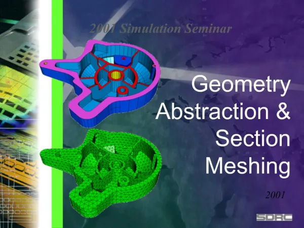

Geometry Abstraction Section Meshing
E N D
Presentation Transcript
1. Geometry Abstraction & Section Meshing
2. Geometric Abstraction and Meshing
3. Quickly pass through the model construction phase
Engineering begins after the results are available Geometry Effects
4. A Break-Down of the CAE Process What is the most time consuming process?
5. Direction of SDRC�s CAE Much Focus on Pre-Processing
Automatic & Robust Tool for building FE Model
6. Improvements during MS5 - MS7 Some examples of the reduction time to build FE Model
7. Powerful Geometry Abstraction Part contains 300 surfaces. Abstracted to 24 meshing regions
8. Customer Endorsements ZF Automotive supplier to many major OEM�s of Driveline and chassis technology
Complex parts/assemblies (I.e. transmission cases)
�Almost 30% development time saved by using I-DEAS Section Meshing Technology�
Dr. Kelkel
ZF, Germany
9. Typical Design Geometry Topology Issues
small edges
compound edges
sliver surfaces
high aspect ratio
missing surfaces
topology too detailed
reconstruction
10. Small Edges Force small element edges
Causes high distortions for elements larger than edge
Dictates element size
11. Sliver Surfaces Narrow surface which causes distortions and stretched elements
12. Disconnected Surfaces Surfaces which are not �stitched� together do not share the same edges
Causes discontinuous mesh that do not allow forces to transfer across the discontinuity
13. Poorly Parameterized Surfaces Surfaces which do not have evenly spaced iso lines do not have evenly spaced parameter space in 3D
Results in skewed and stretched elements
Especially in imported geometry
14. Meshing algorithms Bounded by surface shape and boundaries
can distort elements beyond usefulness
dictates element size
15. Section Meshing Expands the boundaries of surfaces
relaxes mesh area therefore improving quality of elements
removes boundary and shape constraints that negatively effects meshing
16. Section Meshing Permits edge connectors to be removed
Removes requirement of having at least one element/edge
Relaxes elements and therefore improves mesh quality
17. Too Much Detail Small holes usually have adverse effect on mesh
increases number of nodes/elements in unimportant area of model
can distort elements because of local curvature
but are internal boundaries which meshing algorithms must address
18. Too Much Detail Often only one single node is needed to represent hole for boundary condition definition
model more efficient
19. Too Much Detail Topology Suppression
History Supported
requires integrated modeler
Automatic / Manual Modes
Loop Collapsed to Point
Curve Collapsed to Point
Ignores Small Edges
20. Solid Meshes Section meshing applies to solids also
Sections can be used to map mesh volumes for brick elements generation
21. Section Meshing Capture Analysis Intent
User Control
Puts the model size (degrees of freedom) within the control of the user
Does not change the geometry (surfaces, edges, . ) of the part
Overhead minimal because no additional geometry is created
all nodes are on original surfaces and elements can span surface boundaries
Integrity of part is intact
22. Where do I start? I know I can abstract my model but with complex models
How do I find the problem areas?
What element size should I use?
How much time should I spend abstracting?
23. Where Do I Start? Real Parts
Automatically combine surfaces until user criteria is met
24. Surface and Section Quality Checks The meshing job is a balance of FEM size (element size) and how much interaction the user wants to go through to get the element size he wants
In the past modeling time was unpredictable because it was impossible to anticipate how many of these problem situations would arise
25. Quality Check Find small edges
Find sliver surfaces
Find small holes
Show me expendable connectors
26. Quality Checks Highlight problem geometry
27. Quality Checks How many bad surfaces do I have?
Indicates
how much work I have to do to make useable mesh based on criteria
if not many I know what element size this geometry will take
if checks are made on sections, then same indications are available and user knows how much work is left
Continue until all sections disappear
28. Section Mesh Layout
29. Approach Natural operation - editing the wireframe - interactive
Add / Remove / Replace
Loops
Curves
Connectors
Build sections on all surfaces
Addressed isthmus, sliver topology
UI consistency
Additional Functionality
Robust auto create
Extended loop modification commands
30. I-DEAS 8 - Procedure New Auto create
Intelligent methods deployed to generate desired sections
User controlled
Conservative section generation
95% of generated section are meshable
Wireframe edits
Easy modification of the sections once all are defined
Consistent UI (Add / Remove / Replace)
Sections will rebuild after modifications without being deleted
Full Process supported
Other commands that enable the overall process
Meshability check (Enhancement of existing check)
New Manual element tools to correct resulting mesh
Surface Patch Generation
31. Performance Increased performance of sections generate on large models
Wireframe edits are interactive regardless of model size
New Auto create yields a base set of sections that are usable
User now in a modify mode
Highlights the strength and performance of the edit commands
Extendable for better section generation
For multi-surfaced sections use Meshability Check to verify limitations are not violated
Feedback indicates where problem may be if check fails
32. Workflow Workflow
Auto Generate Sections
Perform meshability check
Perform section check
Perform section free curve check
Evaluate abstraction
Wireframe Edits
Target areas that need additional abstraction or modification for meshability
Interactive commands allow user to quickly complete the abstraction
Perform meshability checks as the user edits the sections
Mesh sections
Apply geometry based boundary conditions AFTER section meshing
33. Results
34. Results
35. Results
36. MS8 Replace Curve
37. Replace Curve
38. Replace Curve
39. Mid-Surface Challenges for Section Mesh
40. Section Add Curve
41. Gap too large for auto section to close
42. Project surface boundary and replace
43. Quality Checks All geometric problems anticipated
Meshing reduced to one iteration in most cases
44. Meshing Issues - Tet Hex Tet Hex meshing allow mixing of Parabolic Tets with Bricks
Multipoint Constraint elements (MPCs) tie up loose mid nodes
45. Meshing Issues - Manual Control
46. Meshing Issues - Manual Control
47. Meshing Issues Element Collapse (under the Quality Checks icon stack)
Collapse narrow (stretched) linear or parabolic triangular shells
48. Mesh Generations Brick Elements from shell projection
49. Mesh Generation Project Elements to Surface
50. Augmentation of Geometry Geometric information; physical representation
Additional structure.
Calculation surface to measure energy propagation.
Contact regions, FEM or geometry based.
Weld attachments, reference series of locations
Non-geometric information; non-physical representation
interpolated surfaces.
lumped masses, springs, or beams.
gaps, coupled dofs, or constraint equations.
51. Adaptation of the FEM Associative to design definition
geometry change
abstraction change
boundary conditions
loading conditions
surface mapping
Surface mapping/compare parts
domestic/imported
52. Mesh Generation Many new options and features for mesh construction, including:
Automatic tetrahedral to hexahedral interface
Create Thickness Results
Element Extrude Normal
Element Project
Element Collapse
53. Improve Elements� Quality Nodes Drag
Viewing quality values
Improve surface mesh quality
Auto Settings during meshing
Automatic Mesh Checking & Improvement
Tetra Fix
Move Mid Nodes + Straighten Edge
Plump
Fix Flat tet elements
54. Integrated CAE with 3D/CAD Surfaces Mapping
Imported Geometry from other CAD
55. Surface Mapping Can foreign CAD geometry be Associative to FE data?
What if the model is a mixture of foreign CAD surfaces and I-DEAS generated geometry complete with history?
56. Surface Mapping Section meshing used to define meshing regions
57. Surface Mapping New design introduced from packaging detail design work
User can map new surfaces, edges, and surface normals into correct orientation for feature replacement
58. Surface Mapping Associativity reintroduced to the FEM from the mapping process
Additional features beyond mapped geometry automatically maintained
59. Non-geometric Representation Midsurface
Weld points
usually modeled with rigid elements or couples
Rigid bodies which I do not want to mesh
usually modeled with lumped masses and rigid element
issues about connections and associativity
Connections to other components which transfer force but not infinitely stiff
most conveniently modeled between two point with beams and possibly use of some rigid elements
bolt connections
Contacting surfaces between two bodies or portions of same part
60. Non-Geometric entities Rigid elements for U joint link
Automated meshers need to recognize connection points between nodes on the hole and rigid element connections
61. Non-Geometric entities Spring elements and lumped masses need to be associative to the model which are meshed on modeled geometry
62. Non-Geometric Entities
63. Spot Weld Automatic meshing of entities without geometry
64. Non-Geometric entities Lumped mass for CG of connecting body
Rigid element network for force distribution to center of mass
65. Summary Section meshing has become the preferred meshing approach to all model situations where shell and solid elements are automatically generated
Geometry playing a more important role in FE efficiency
for the CAE processes to have a more positive impact on the design
to make it a reality to evaluate as many design alternatives
automatically update the design from parameter studies and optimization activities
66. Future Development Further abstraction of outer boundary of section to remove narrow sliver areas without having to expand to neighboring surface
Abstraction via feature recognition
make a beam abstraction from 3D geometry (stiffeners)
select surfaces
software automatically creates cross section properties
define connection information to rest of model
Automatic multi-surface section definition based on element size selection
Expand the element support to entire element library