Download

1 / 55
550 likes | 578 Vues
Learn about the challenges and importance of beam loss and collimation at the LHC, including the role of collimators in machine protection.

E N D
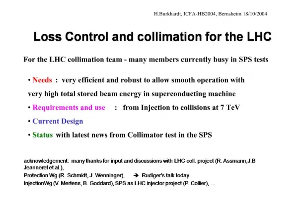
Beam Loss and Collimation at the LHC R. Assmann, CERN/AB 15/11/2007 for the Collimation Team GSI Beschleunigerpalaver
What is the LHC Beam? Protons/ions stored in circular accelerator. Particles travel with light velocity in a 27 km long vacuum tube. Revolution frequency is 11 kHz. Ideally fully stable without any losses. Two beams with opposite travel directions and well defined collision points. Top view p 7.6 cm 0.2 mm 25 ns 25 ns
1) Introduction: The LHC Challenge Number of bunches: 2808 Bunch population: 1.15e11 Bunch spacing: 25 ns Top energy: Proton energy: 7 TeV Transv. beam size: ~ 0.2 mm Bunch length: 8.4 cm Stored beam energy: 360 MJ Injection: Proton energy: 450 GeV Transv. Beam size: ~ 1 mm Bunch length: 18.6 cm The Large Hadron Collider: Circular particle physics collider with 27 km circumference. Two colliding 7 TeV beams with each 3 × 10¹⁴ protons. Super-conducting magnets for bending and focusing. Start of beam commissioning: May 2008. Particle physics reach defined from: 1) Center of mass energy 14 TeV super-conducting dipoles 2) Luminosity 1034 cm-2 s-1 LHC nominal parameters
LHC Luminosity • Luminosity can be expressed as a function of transverse energy densityre in the beams at the collimators: • Various parameters fixed by design, for example: • Tunnel fixes revolution frequency. • Beam-beam limit fixes maximum bunch intensity. • Machine layout and magnets fix possible demagnification. • Physics goal fixes beam energy. • Luminosity is increased via transverse energy density! d = demagnification (bcoll/b*) Np = protons per bunch frev = revolution freq. Eb = beam energy
pp, ep, and ppbar collider history Higgs + SUSY + ??? ~ 80 kg TNT 2008 Collimation Machine Pro-tection 1992 SC magnets 1971 1987 1981 The “new Livingston plot“ of proton colliders: Advancing in unknown territory! A lot of beam comes with a lot of garbage (up to 1 MW halo loss, tails, backgrd, ...) Collimation. Machine Protection.
Proton Losses • LHC: Ideally no power lost (protons stored with infinite lifetime). • Collimators are the LHC defense against unavoidable losses: • Irregular fast losses and failures: Passive protection. • Slow losses: Cleaning and absorption of losses in super-conducting environment. • Radiation: Managed by collimators. • Particle physics background: Minimized. • Specified 7 TeV peak beam losses (maximum allowed loss): • Slow: 0.1% of beam per s for 10 s 0.5 MW • Transient: 5 × 10⁻⁵ of beam in ~10 turns (~1 ms) 20 MW • Accidental: up to 1 MJ in 200 ns into 0.2 mm2 5 TW
The LHC Collimators… • Collimators must intercept any losses of protons such that the rest of the machine is protected („the sunglasses of the LHC“): > 99.9% efficiency! • To this purpose collimators insert diluting and absorbing materials into the vacuum pipe. • Material is movable and can be placed as close as 0.25 mm to the circulating beam! • Nominal distance at 7 TeV: ≥ 1 mm. • Presently building/installing phase 1! Top view
Preventing Quenches • Shock beam impact: 2 MJ/mm2 in 200 ns (0.5 kg TNT) • Maximum beam loss at 7 TeV: 1% of beam over 10 s 500 000 W • Quench limit of SC LHC magnet: 8.5 W/m
Machine Protection • There are a number of LHC failure scenarios which lead to beam loss. • No discussion of machine protection details here. However, comments on collimator role in machine protection. R. Schmidt is Project Leader for MP. • Slow failures: • First losses after >10-50 turns appear at collimators as closest aperture restrictions. • Beam loss monitors detect abnormally high losses and dump the beam within 1-2 turns. • Fast failures (dump and injection kicker related): • Sensitive equipment must be passively protected by collimators. • In all cases, the exposed collimators must survive the beam impact:up to 2 MJ in 200 ns (0.5 kg TNT)
2) LHC Collimation Basics Beam axis Beam propagation Impact parameter Collimator Core Particle Unavoidable losses Primary halo (p) Multi-Stage Cleaning Secondary halo p p Shower p Tertiary halo Impact parameter ≤ 1 mm p e p Primary collimator Secondary collimator Shower e SC magnets and particle physics exp. Absorber Super-conducting magnets Absorber W/Cu W/Cu CFC CFC
System Design “Phase 1” Momentum Collimation Betatron Collimation “Final” system: Layount is 100% frozen! C. Bracco
LHC Collimator Gaps • Collimator settings: • 5 - 6 s (primary) • 6 - 9 s (secondary) • s ~ 1 mm (injection) • s ~ 0.2 mm (top) • Small gaps lead to: • Surface flatness tolerance (40 mm). • Impedance increase. • Mechanical precision demands (10 mm).
Required Efficiency Quench threshold (7.6 ×10⁶ p/m/s @ 7 TeV) Allowed intensity Illustration of LHC dipole in tunnel Cleaning inefficiency = Number of escaping p (>10s) Number of impacting p (6s) Beam lifetime (e.g. 0.2 h minimum) Dilution length (~10 m) Collimation performance can limit the intensity and therefore LHC luminosity.
Intensity Versus Cleaning Efficiency For a 0.2 h minimum beam lifetime during the cycle. 99.998 % per mefficiency
The LHC Phase 1 Collimation • Low Z materials closest to the beam: • Survival of materials with direct beam impact • Improved cleaning efficiency • High transparency: 95% of energy leaves jaw • Distributing losses over ~250 m long dedicated cleaning insertions: • Average load ≤ 2.5 kW per m for a 500 kW loss. • No risk of quenches in normal-conducting magnets. • Hot spots protected by passive absorbers outside of vacuum. • Capturing residual energy flux by high Z absorbers: • Preventing losses into super-conducting region after collimator insertions. • Protecting expensive magnets against damage. • No shielding of collimators: • As a result radiation spread more equally in tunnel. • Lower peak doses. • Fast and remote handling possible for low weight collimators.
Hardware: Water Cooled Jaw • Up to 500 kW impacting on a jaw (7 kW absorbed in jaw)… Advanced material: Fiber-reinforced graphite (CFC)
The LHC “TCSG” Collimator 1.2 m 360 MJ proton beam Research topic:Advanced mechanical engineering 3 mm beam passage with RF contacts for guiding image currents Designed for maximum robustness: Advanced CC jaws with water cooling! Other types: Mostly with different jaw materials. Some very different with 2 beams!
Robustness Test with Beam C-C jaw Research topic:Advanced materials and extreme shock waves TED Dump C jaw 450 GeV 3 1013 p 2 MJ 0.7 x 1.2 mm2 Microphone Graphite Fiber-reinforced graphite (CFC) ~ Tevatron beam ~ ½ kg TNT
Using Sensors to Monitor LHC Jaw Positions Side view at one end Research topic: Precision remote control and survey Vacuum tank Movement for spare surface mechanism (1 motor, 2 switches, 1 LVDT) CFC CFC Temperature sensors Microphone Reference Reference Motor Motor Sliding table Gap opening (LVDT) Resolver Resolver Gap position (LVDT) + switches for IN, OUT, ANTI-COLLISION
Collimator Controls S. Redaelli et al Collimator Beam-Based Alignment Successful test of LHC collimator control architecture with SPS beam (low, middle, top level)
Position Measurement and Reproducibility 20 µm ~ 25 µm mechanical play R. Losito et al • Measured during test in TT40 (Oct. 31st) in remote!!!!
Compatibility with LHC UHV Research topic: Energy absorption in Ultra High Vacuum J-P. BOJON, J.M. JIMENEZ, D. LE NGOC, B. VERSOLATTO Conclusion: Graphite-based jaws are compatible with the LHC vacuum. The outgassing rates of the C jaws will be optimized by material and heat treatment under vacuum, an in-situ bake-out and a proper shape design. No indication that graphite dust may be a problem for the LHC.
Other collimator features • In-situ spare concept by moving the whole tank (move to fresh surface if we scratch the surface with beam) • Direct measurements of jaw positions and absolute gap (we always know where the jaws are) • Precision referencing system during production • Measurements of jawtemperature • Radiation impact optimization: Electrical and water quick plug-ins, quick release flanges, ceramic insulation of cables, ... • RF contacts to avoid trapped modes or additional impedance C. Rathjen, AT/VAC
Collimator Deliveries Production deadline for initial installation Initial 7 TeV installation Industry:87% of production for 7 TeV initial ring installation has been completed (66/76). All collimators for first run should be at CERN by end of the year. Total production should be completed in April.
4) Tunnel Installations(vertical and skew shown) Water Connections Vacuum pumping Modules Collimator Tank (water cooled) Quick connection flanges BLM Beam 2 A. Bertarelli
Tunnel Preparations IR7 Cable routing from top (radiation) Water connection Cable trays Pumping domes Series of collimator plug-in supports
Collimator Installation Quick plug-in support (10 min installation)
Installed Collimator on Plug-In Collimator Upper plug-in Lower plug-in Base support
Remote Train Research topic: Remote handling in radioactive environment
4) Collimation Performance Simulations:5 million halo protons 200 turns realistic interactions in all collimator-like objects LHC aperture model Multi-turn loss predictions
Efficiency in Capturing Losses Research topic: Halo andcollimation modeling Beam1, 7 TeV Betatron cleaning Ideal performance TCDQ Efficiency 99.998 % per m Quench limit (nominal I, t=0.2h) Local inefficiency [1/m] Beam2, 7 TeV Betatron cleaning Ideal performance TCDQ Efficiency 99.998 % per m Quench limit (nominal I, t=0.2h) 99.998 % needed 99.995 % predicted Local inefficiency: #p lost in 1 m over total #p lost = leakage rate
Problem: Beam loss tails? Research topic: Halo beam dynamics and diffusion theory Observation of BLM signal tails: Up to 10-20 seconds in length BLM team: Many measurements Beam related true signal!
Collimation for Ions Different physics! Two-stage b cleaning not working! Limitation to ~50% of nominal ion intensity. Research topic: Ion collimation and ion losses G. Bellodi et al Power load [W/m] Loss predictions used for allocation of additional BLM’s for ions!
Energy Deposition (FLUKA) K. Tsoulou et al Research topic: Energy deposition FLUKA team
CERN Mechanical Simulations Displacement analysis – Nominal conditions (100 kW) – Load Case 2 10s Transient (500 kW) – Loss rate 4x10¹¹ p/s (Beam Lifetime 12min) Research topic:Advanced thermo mechanical modeling Initial loss 8e10p/s Max. deflect. ~20mm Transient loss 4e11p/s during 10s Max deflect. -108mm Back to 8e10p/s situation! A. Bertarelli & A. Dallochio
Local Activation • Losses at collimators generate local heating and activation. • Local heating: On average 2.5 kW/m. • Activation: Up to 20 mSv/h on contact (better not touch it). • Fast handling implemented. Remote handling being developed. Research topic: Radiation impact Residual dose rates One week of cooling S. Roesler et al
Kurchatov Collaboration Studies of CFC Material Used in LHC Collimators Research topic: Radiation damage in accelerator materials A. Ryazanov Working on understanding radiation damage to LHC collimators from 1016 impacting protons of 7 TeV per year. Also with BNL/LARP… … in addition shock wave models…
Impedance Problem Third look at impedance in Feb 03 revealed a problem: F. Ruggiero • Several reviews of LHC collimator-induced impedance (originally not thought to be a problem). • Surprise in 2003: LHC impedance driven by collimators, even metallic collimators. • LHC will have an impedance that depends on the collimator settings! • Strong effort to understand implications… Research topic:Impedance
First Impedance Estimates 2003 Typical collimator half gap 104 103 102 LHC impedance without collimators Transverse Impedance [MΩ/m] 10 1 10-1 0 2 4 6 8 10 Half Gap [mm] F. Ruggiero, L. Vos
Impedance and Chromaticity E. Metralet al
2006 Collimator Impedance Measurement • Improved controls in 2006: • Possibility of automatic scan in collimator position. • Much more accurate and complete data set in 2006 than in 2004! R. Steinhagen et al E. Metral et al
Summary: The Staged LHC Path * Limited by cleaning efficiency (primary) and impedance (secondary)
5) Beyond Phase 1 • The LHC phase 1 system is the best system we could get within the available 4-5 years. • Phase 1 is quite advanced and powerful already and should allow to go a factor 100 beyond HERA and TEVATRON. • Phase 2 R&D for advanced secondary collimators starts early to address expected collimation limitations of phase 1. • Phase 2 collimation project was approved and funded (CERN white paper). Starts Jan 2008. Should aim at complementary design compared to SLAC. • Collaborations within Europe through FP7 and with US through LARP are crucial components in our plans and address several possible problems. • We also revisit other collimation solutions, like cryogenic collimators, crystals, magnetic collimators, non-linear schemes.
LHC Phase 2 Cleaning & Protection Secondary halo p p e p Primary collimator Crystal Phase 1 Colli-mator TCSG Phase 1 Colli-mator TCSG Hybrid Colli-mator TCSM Shower Primary collimator CFC CFC Phase 2 material CFC CFC & Crystal Beam axis Beam propagation Impact parameter Collimator Core Particle Unavoidable losses • Phase 2 materials for system improvement. • Crystals AP under study (surface effects, dilution, absorption of extracted halo). Primary halo (p) Shower Tertiary halo p Impact parameter ≤ 1 mm p e SC magnets and particle physics exp. Absorber Super-conducting magnets Absorber W/Cu W/Cu Low electrical resistivity, good absorption, flatness, cooling, radiation, …