This presentation is driven by the mouse or pointing device.
270 likes | 286 Vues
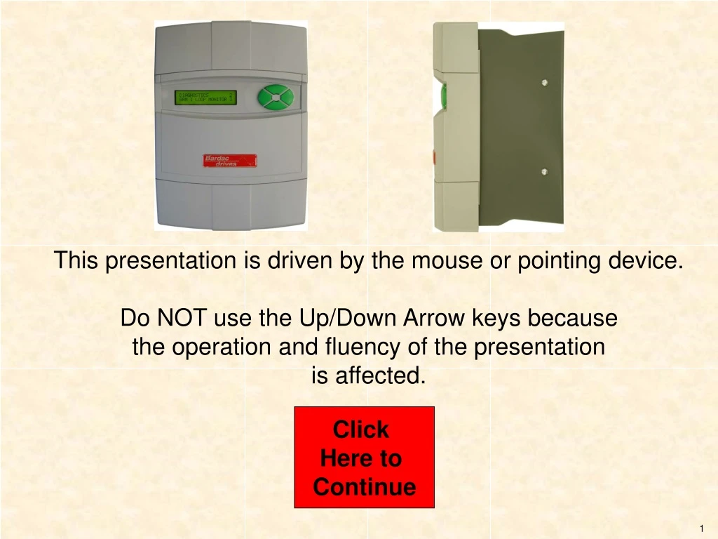
This presentation is driven by the mouse or pointing device. Do NOT use the Up/Down Arrow keys because the operation and fluency of the presentation is affected. Click Here to Continue. PL & PLX Series. DC Drive Product Family from. PL/X Digital Drive. Introduction. Product Data.

This presentation is driven by the mouse or pointing device.
E N D
Presentation Transcript
This presentation is driven by the mouse or pointing device. Do NOT use the Up/Down Arrow keys because the operation and fluency of the presentation is affected. Click Here to Continue
PL & PLX Series DC Drive Product Family from
PL/X Digital Drive Introduction Product Data Key Features Drive Connections Menu Concepts Exit
Introduction • The PL/PLX DC drive family is a totally digital DC drive using state of the art software to provide the user with an outstanding range of standard features. • It has outstanding dynamic performance, a wide power range, 2 or 4 quadrant operation,clear display with finger friendly keypad and compact size. • PL/PLX drive…the benchmark for DC Drives.
Operator Interface • Multifunction LCD Display. • 40 Character 2 Line. • Backlit when active. • Very clear to read. • English language parameters. • Multi language options (T.B.A.) • 4 Button Keypad • Easy to learn and use • Finger Friendly keys Previous Next Home Page
All analog input voltages All digital input states All analog output voltages All digital output states Tachometer volts Motor armature current Motor field current Motor armature volts Output power (KW) AC supply volts Performance and Diagnostics • Steady State Accuracy • 0.01% with Encoder + Digital Ref • 0.1% with Tachometer feedback • 2.0% with AVF Diagnostic Monitoring Previous Next Home Page
Interline Device Networks High Energy MOV’s Instantaneous Overcurrent Stall Protection Field Failure & Overcurrent Motor Over-temperature Armature Overvolts Thyristor Trigger failure Standstill logic Stack Over-temperature Mains supply phase loss Mains synchronization loss Digital Output short circuit Power Chassis Features • Outstanding Protection Previous Next Home Page
Field Regulator Feature • Field Modes • Constant current • Constant voltage • Automatic weakening • Economy mode • Delayed quench after stop command • Supply independent of stack supply Previous Next Home Page
2 PID’s 2 Filters 2 Summers or Adders Current Profiling Batch Counter Latch Linear or S ramp Jog / Crawl Functions Center Winding Macros Motorized Pot Field Weakening Dual Motor Swap Zero Speed Position Lock Delay Timer Draw Control Auto Self-tune Current Loop Application Blocks Function Block Programming The following function blocks are included as standard: Previous Next Home Page
Digital IO Configurability • 17 Digital Inputs • All inputs are over-voltage protected • 7 Digital Outputs • All outputs are over-voltage protected • All Digital I/O short circuit proof Previous Next Home Page
Analog IO Features • Analog inputs • 8 Independent inputs of upto 5 mV resolution. • Digital threshold function with dual action. • Analog outputs • 4 Outputs, 1 dedicated to Output current • 3 fully programmable, 12 bit resolution. • All Analog Inputs are over-voltage protected • All Analog Outputs are short circuit protected Previous Next Home Page
Out-of-Box Features • Five feedback transducer options as standard • Non volatile trip alarm memory - even after power-loss • Real language parameter description eliminates need for look up tables • Motor parameters entered via keys - no soldering of calibration resistors required • Motorized pot simulator with power off memory Previous Next Home Page
Commissioning Features • Built in “Oscilloscope” output for full parameter monitoring during commissioning • Unique “Configuration checker” detects shorting of user programmed block diagram outputs • Unique electronic regenerative stopping facility on most 2 Quadrant models • Built in system application blocks with descriptive connection points Previous Next Home Page
Other Features • In depth fault monitoring and comprehensive system alarms • Serial communications to allow off site programming and remote diagnostics • In depth diagnostic facility available from on board display and “in-built meter” • Easy to use product manual with display graphics and block diagrams Previous Next Home Page
Horsepower & Current Ratings • Field Amps • Std Opt • 8 - • 8 - • - • 8 - • 16 - • 16 - • 16 - • - • 32 50 • 32 50 • 32 50 DC Amps Continuous 36 51 99 123 164 205 270 330 405 480 630 HP @ 240VDC 10 10 25 35 50 60 75 100 125 150 200 HP @ 500VDC 20 30 60 75 100 125 150 200 250 300 350 Drive Model PL / PLX 15 PL / PLX 20 PL / PLX 40 PL / PLX 50 PL / PLX 65 PL / PLX 85 PL / PLX 115 PL / PLX 145 PL / PLX 185 PL / PLX 225 PL 265 only Previous Next Home Page
Dimensions Frame Size H x W x D 11.4 x 8.5 x 6.9 in 289 x 216 x 174 mm 16.2 x 8.5 x 8.6 in 410 x 216 x 218 mm 19.9 x 8.5 x 11.6 in 505 x 216 x 294 mm HP @ 240VDC 10 10 25 35 50 60 75 100 125 150 200 HP @ 500VDC 20 30 60 75 100 125 150 200 250 300 350 Drive Model PL / PLX 15 PL / PLX 20 PL / PLX 40 PL / PLX 50 PL / PLX 65 PL / PLX 85 PL / PLX 115 PL / PLX 145 PL / PLX 185 PL / PLX 225 PL 265 only Previous Next Home Page
Supply Voltages • Main Supply for Armature • 12 to 480 VAC, 3 phase, 50 to 60 Hz +10% • Auxiliary Supply for Field • 100 to 480 VAC, 3 phase, 50 to 60 Hz +10% • Control Supply • 100 to 240 VAC, 1 phase, 50 to 60 Hz +10% • Note:- On PL/PLX 185 to 265, a 50va 110VAC 50/60 Hz supply is needed for fans. Previous Next Home Page
Output Voltages • Armature • PL range: 0 to 1.2 x Supply voltage • PLX range: 0 to +1.2 x Supply voltage • Field • All models: 0 to 0.9 x Supply voltage. Previous Next Home Page
DC Motor General Connections Field Armature Blower Motor Tacho Encoder Thermistor To Blower Motor control + B A 24V A+ A- F- F+ 30 25 26 13 16 17 35 Previous Next Home Page
Control Connections 1 2 3 4 5 6 7 8 9 10 11 12 13 14 15 16 17 18 19 20 21 22 23 24 25 26 27 28 29 30 31 32 33 34 35 36 41 42 43 44 45 46 47 48 49 50 The PL/PLX drive control connections are on 4 sets of terminals. For a detailed description, click on the specification button. Analog Inputs and Outputs Digital Inputs and Outputs Specific Inputs and Outputs Misc Inputs and Outputs Specification Specification Specification Specification Home Page
Analog Inputs and Outputs 1 2 3 4 5 6 7 8 9 10 11 12 Short Form 0 V UIP2 UIP3 UIP4 UIP5 UIP6 UIP7 UIP8 UIP9 AOP1 AOP2 AOP3 Terminal No. UIP Data Upto 5mV resolution + sign Assignable voltage range (+/- 5/10/20/30 volt) Built in comparator with adjustable threshold & dual result monitor. UIP3 is extra high performance for current loop use. Max & Min Clamps: Linear Scaling Function: Linear Offset Function: AOP Data 12 bit resolution + sign Short Circuit Protection to 0V Output + 0 - 5mA maximum Output range +0 - 11.0 volts (10V = 100%) Previous
Digital Inputs and Outputs 13 14 15 16 17 18 19 20 21 22 23 24 Short Form 0 V DIP1 DIP2 DIP3 DIP4 DIO1 DIO2 DIO3 DIO4 DOP1 DOP2 DOP3 Terminal No. Digital inputs for logic or incremental encoder data. Invert function Can be digital input or digital output. When used as output, the input mode continues to function and the terminal state is monitored. 350mA max per output. 350mA total output budget. Default outputs are: Zero speed, At Speed & Drive Healthy. 350mA max per output. 350mA total output budget. Previous
Specific Inputs and Outputs 25 26 27 28 29 30 31 32 33 34 35 36 Short Form 0 V Tacho +10V -10V IArm Therm Run Jog Start CStop +24V 0 V Terminal No. Motor mounted Tachometer Analog Reference Voltages Run Jog Start Previous
Misc. Inputs and Outputs Short Form RA+ not used RA- not used CON 1 CON 2 LAT1 LAT2 Earth N L Terminal No. 41 43 45 46 47 48 51 52 53 These terminals must be used to sense the armature voltage when field weakening with a DC side contactor. These terminals are volt-free contacts of internal relay for main contactor control. Rating 240 V, 500VA. These terminals are volt-free contacts of internal relay for latching a start pushbutton. Rating 240 V, 500VA. These terminals are for 100 - 240 VAC control supply @ 50VA. Previous
Menu Structure • The Menu structure is very simple and, most importantly, easy to operate. • There are 5 levels, each one allowing you to step through a tree structure of logical parameter groups. Previous Next Home Page
Menu Control Down Key scrolls the menu and Decreases the parameter value Up Key scrolls the Menu and Increases the Parameter value Right Key moves to next menu level Left Key moves to previous menu level Previous Home Page Next