Download
1 / 12
120 likes | 228 Vues
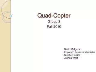
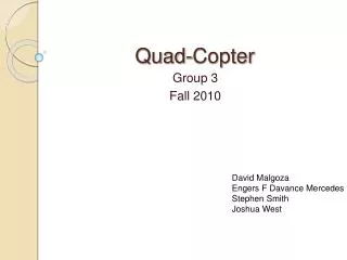
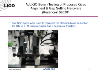
Ideal Order of QUAD Testing. J. Kissel, S. Aston for the SUS Team G1100693-v5. Driving Principles. Learn as much as you can about the systems, as early as possible Assembly and Testing are synonomous, not separate, as should be the teams

E N D
Ideal Order of QUAD Testing J. Kissel, S. Aston for the SUS Team G1100693-v5 G1100693-v5
Driving Principles • Learn as much as you can about the systems, as early as possible • Assembly and Testing are synonomous, not separate, as should be the teams • Test simple cases first, then your understanding of the full thing will be more clear • Test report should contain everything you need to *prove* it works, but does not contain every test you’ve done to *make* it work (Results vs. Tests vs. Sanity Checks) • We’re still developing the production line – not all tests that we’ve [done in the past / will do in the future] are useful, but we don’t know until we try • This is an ideal list. Reality maybe force us to measure less. We need not go back and get results, if the oppurtunity has passed. • We care about the performance / response / reports in the final configuration (fiber build, fully assembled, in-vac) the most G1100693-v5
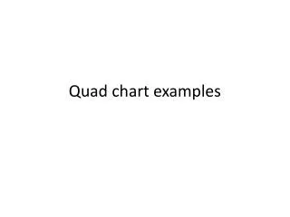
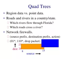
Order of Operations - LINGO Phase 1a Metal Build, Assembly & Tests Phase 2a Metal Build, Fully Assembled Sanity Checks Phase 3a Phase 1b Fiber Build, In-Chamber, In-Air Testing Metal Build, Fully Assembled Testing Commissioning Move full assembly to Chamber-Side (from storage or assembly area) Acceptance! Phase 2b Fiber Build, In-Chamber Testing Lower Half Fiber Build, Assembly & Tests Phase 3b Fiber Build, In-Chamber, In-Vacuum, Testing Cartridge Install Phase 2c Fiber Build, Fully Assembled Testing G1100693-v5
LINGO – Stages of Testing Phase 2a Phase 1b Phase 2c Phase 1a Phase 2b Phase 3a & 3b Commissioning G1100693-v5
Phase 1a Wire Build, Assembly and Testing • Tests • DC Alignment (from Levels and Optical Levers) • Magnet Polarity Check • Ensure appropriate model infrastructure has been restored • Determine M0, R0, L1, L2 Open Ligh Current Results • Main Chain (MC), Reaction Chain (RC) suspended mass’ mass (ICS) • Trim mass allocation at all stages (ICS) • Blade Characterization Data (Stiffness Pass/Fail) • M0, R0, L1, L2 Magnet Strength Data (Strength Pass/Fail) (Manufacturer’s Spec) (Merely ensure that all specs are in hand) • M0, R0, L1, L2 OSEM Inventory; S/N, Configuration, Open Light Voltage (Open Light Voltage Pass/Fail) (Update ICS, Update OSEM Chart E1200343) • M0, R0, L1, L2 OSEM Coil Resitance and Inductance (Tolerance Pass/Fail) (Merely ensure that all data is in hand) • M0, R0, L1, L2 OSEM sensor noise assessment (Noise Floor Pass/Fail) (Merely ensure that all data is in hand) • Individual Vibration Absorber Characterization (Resonant Bandwidth Pass/Fail) (Merely ensure that all data is in hand) G1100693-v5
“Top to Top” = M0 to M0 & R0 to R0 Phase 1b Wire Build, Fully Assembled Testing • Tests • DC Alignment/Balancing (from Optical Levels and Levers) • Ability to Sense M0, R0 • M0, R0 OSEM Centering • M0, R0 OSEM Sensor Diagonalization / Perpendicular Alignment • M0, R0 Sensor Sign Checks • Expected Watchdog behavior • Ability to Actuate M0, R0 • M0, R0 Actuator Sign Checks • Reaction Chain Cable Dressing • Rough L1, L2 OSEM Centering and alignment • L1, L2 Sensor Sign Checks • Rubbing Checks (EQ Stops, etc) • Damping Loop Closure Physically Move M0,R0 Use speedometers Take single-frequency V & Y Top to Top TFs Results • Phase 1 SUS alignment assessment (Tolerances Pass/Fail) • Final Calibrated OSEM Spectra of M0, R0, L1, L2 Motion (Resonances & Noise Floor Pass/Fail) • Comparison Set (Euler and OSEM Basis ASDs, compared with single Reference Measurement) • Final Calibrated Top to Top Transfer Functions, Euler and OSEM basis, Damping Off, (Model and Ref. Meas. Comparison Pass/Fail) • Individual Set (Euler and OSEM Basis TFs, compared with Model ) • Comparison Set (Euler Basis only, compared with Reference Measurements and Model) • Final Calibrated Top to Top Transfer Functions, Euler and OSEM basis, Damping ON (Model and Ref. Meas Comparison Pass/Fail) • Individual Set (Euler and OSEM Basis TFs, compared with Model ) • Comparison Set (Euler Basis only, compared with Reference Measurements and Model) Physically Move M0,R0 DC Offsets Take a set of Top to Top TFs Take a set of Top to Top TFs Use speedometers Top DC Offsets Take a set of Top to Top TFs G1100693-v5
“Top to Top” = M0 to M0 & R0 to R0 Phase 2a Wire Build, Fully Assembled Sanity Checks • Tests • DC Alignment/Balancing (from Optical Levels and Levers) • Ensure front-end model infrastructure is in place • Determine M0, R0, L1, L2 OSEM Open Light Current • Center M0, R0, L1, L2 OSEMs • Ability to Sense M0, R0 • M0, R0 Sensor Sign Checks • Expected Watchdog behavior • Coil Driver BIO switches’ functionality confirmed • Ability to Actuate M0, R0 • Rubbing Checks (EQ Stops, etc) • Ability to Sense L1, L2 • Damping loop closure Use speedometers Results • M0, R0, L1, L2 OSEM Open Light Current (Open Light Current Level Pass/Fail) (Updated OSEM Chart E1200343) • Final Calibrated OSEM Spectra of M0, R0, L1, L2 Motion (Resonances & Noise Floor Pass/Fail) • Comparison Set (Euler and OSEM Basis ASDs, compared with single Reference Measurement) • Comparison Set (Euler and OSEM Basis ASDs, compared with Prior Stage Results) • Final Calibrated Top to Top Transfer Functions, Euler and OSEM basis, Damping Off, (Model and Ref. Meas. Comparison Pass/Fail) • Individual Set (Euler and OSEM Basis TFs, compared with Model ) • Comparison Set (Euler Basis only, compared with Reference Measurements, Prior Stage Results, and Model) • Final Calibrated Top to Top Transfer Functions, Euler and OSEM basis, Damping ON (Model and Ref. Meas Comparison Pass/Fail) • Individual Set (Euler and OSEM Basis TFs, compared with Model ) • Comparison Set (Euler Basis only, compared with Reference Measurements, Prior Stage Results, and Model) Take a Spectra Physically move the Suspension DC Offsets Take a set of Top-Top TFs Take a Spectra G1100693-v5
“Top to Top” = M0 to M0 & R0 to R0 Phase 2b Fiber Build, Assembly and Testing • Tests (Before install of Fiber Protection) • PUM/TST DC alignment in Wire Hang • Check/Record (single) fiber profile • 15 kg load (single) fiber proof test • DC Alignment (from Optical Levels and Levers) • Rubbing checks (EQ Stops, etc.) • Single-hang (PUM Locked) modal frequency assessment (see T1100594) Results • Fiber Characterization Data (Metrology and/or Profile, Load Pass/Fail) (Merely ensure that all data is in-hand) • Ear Characterization Data (Metrology Pass/Fail) (Merely ensure that all data is in-hand) • ESD Characterization (Continuity, Mapping, Metrology Pass/Fail) • Ring Heater Characterization (Continuity Pass/Fail) • Calibrated L, V, P, Y Single Pendula (PUM->TST) Spectra (Resonances Pass/Fail) G1100693-v5
“Top to Top” = M0 to M0 & R0 to R0 Phase 2c Fiber Build, Fully Assembled Testing • Tests • DC Alignment (using Optical Levels and Levers, full IAS Blessing) • Full IAS Alignment Checkout (Test Mass Height, Test Mass/Reaction Mass Gap check, Chain Alignment, etc) • Center M0, R0, L1, and L2 OSEMs • Ability to Sense M0, R0, L1, L2 OSEMs • Expected Watchdog behavior, including interactions with BSC-ISI • Ability to Actuate M0 and R0 • ESD Continuity, Ring Heater resistance • Assess absense of Ground Loops in Cable Routing • Reaction Chain Cable Dressing • Rubbing Checks (EQ Stops, etc.) • Assess Table Mounting / Dog Clamping with B&K Hammer & Accelerometer (Vibration Absorbers OFF) • Assess Vibration Absorber Functionality with B&K Hammer & Accelerometer (Vibration Abosorbers ON) • Damping Loop Closure • Assess Coupling to ISI with BSC-ISI ST2 transfer function Use Speedometers Take Spectra Results • Final IAS alignment checkout (Tolerances Pass/Fail) • Watchdog connection with BSC-ISI, Damping Loop Functionality (Expected Protection Pass/Fail) • Final Calibrated OSEM Spectra of M0, R0, L1, L2 Motion (Resonances & Noise Floor Pass/Fail) • Comparison Set (Euler and OSEM Basis ASDs, compared with single Reference Measurement) • Comparison Set (Euler and OSEM Basis ASDs, compared with previous stage) • Final Calibrated Top to Top Transfer Functions, Euler and OSEM basis, Damping Off, (Model and Ref. Meas. Comparison Pass/Fail) • Individual Set (Euler and OSEM Basis TFs, compared with Model) • Comparison Set (Euler Basis only, compared with Reference Measurements, Previous Stage Results, and Model) • Final Calibrated Top to Top Transfer Functions, Euler and OSEM basis, Damping ON (Model and Ref. Meas. Comparison Pass/Fail) • Individual Set (Euler and OSEM Basis TFs, compared with Model) • Comparison Set (Euler Basis only, compared with Reference Measurements, Previous Stage Results, and Model) • Assess Vibration Absorber Performance (Suitable Reduction of Resonances, Decoupling from ISI Pass/Fail) Take a set of Top-Top TFs Use Digital Multimeter Take a set of Top-Top TFs Take a set of Top-Top TFs G1100693-v5
“Top to Top” = M0 to M0 & R0 to R0 Phase 3a Fiber Build, In-Chamber, In-Air Testing • Tests • Assess electronics chain continuity through feedthrus (ESD continuity, Ring Heater resistance, etc) • Assess cable routing stiffness/compliance from Optical Table, through ISI, to Feedthrough • Determine M0, R0, L1, and L2 Open Light Current • Final Centering of M0, R0, L1, L2 OSEMs (including bouyancy compensation for vertical OSEMs) • Final Setting of EQ Stop Distances (including bouyancy compensation for vertical stops) • Ability to Sense / Actuate M0/R0 • Ability to Sense L1, L2 • Final Rubbing Checks (EQ Stops, etc.) • Damping Loop Closure • Assess coupling to ISI with BSC-ISI ST2 transfer function (if Phase 2c test was polluted by ambient noise) Results • M0, R0, L1, and L2 OSEM Open Light Current (Open Light Current Level Pass/Fail) (Updated OSEM Chart E1200343) • Final Calibrated OSEM Spectra of M0, R0, L1, L2 Motion (Resonances & Noise Floor Pass/Fail) • Comparison Set (Euler and OSEM Basis ASDs, compared with single Phase 3a Reference Measurement) • Comparison Set (Euler and OSEM Basis ASDs, compared with previous stages) • Final Calibrated Top to Top Transfer Functions, Euler and OSEM basis, Damping Off, (Model and Ref. Meas. Comparison Pass/Fail) • Individual Set (Euler and OSEM Basis TFs, compared with Model) • Comparison Set (Euler Basis only, compared with Reference Measurements, Previous Stage Results, and Model) • Final Calibrated Top to Top Transfer Functions, Euler and OSEM basis, Damping ON (Model and Ref. Meas. Comparison Pass/Fail) • Individual Set (Euler and OSEM Basis TFs, compared with Model) • Comparison Set (Euler Basis only, compared with Reference Measurements, Previous Stage Results, and Model) DC Offsets Take a Spectra Take a set of Top-Top TFs Take a set of Top-Top TFs G1100693-v5
“Top to Top” = M0 to M0 & R0 to R0 Phase 3b Fiber Build, In-Chamber, In-Vacuum Testing • Tests • Ability to Sense/Actuate M0, R0, L1, L2, L3 • Rubbing Checks via Transfer Functions Take OSEM/Oplev Spectra Take a set of Top-Top TFs Results • Final Calibrated OSEM Spectra of M0, R0, L1, L2 Motion (Resonances & Noise Floor Pass/Fail) • Comparison Set (Euler and OSEM Basis ASDs, compared with single Reference Measurement) • Comparison Set (Euler and OSEM Basis ASDs, compared with previous stage) • Final Calibrated Top to Top Transfer Functions, Euler and OSEM basis, Damping Off, (Model and Ref. Meas. Comparison Pass/Fail) • Individual Set (Euler and OSEM Basis TFs, compared with Model) • Comparison Set (Euler Basis only, compared with Reference Measurements, Previous Stage Results, and Model) • Final Calibrated Top to Top Transfer Functions, Euler and OSEM basis, Damping ON (Model and Ref. Meas. Comparison Pass/Fail) • Individual Set (Euler and OSEM Basis TFs, compared with Model) • Comparison Set (Euler Basis only, compared with Reference Measurements, Previous Stage Results, and Model) • Final Calibrated L1, L2 to L1, L2, L3 Transfer Functions, Euler Basis, Damping Off (Model and Ref. Meas. Comparison Pass/Fail) • M0, L1, L2 Actuation Range Test using OSEMs (or OpLev if available) • L3 Actuation Range Test using OpLev ACCEPTANCE!! G1100693-v5
“Top to Top” = M0 to M0 & R0 to R0 Commissioning In-Chamber, as part of IFO Goals • OSEM Spectra of M0, R0 Motion, compare with Phases 2c, 3a, 3b, with BSC-ISI/HEPI in various states (ON/OFF, Damping ON/OFF, Low/High Perf, etc. etc.) • M3 Motion measured by IFO, compare with Phases 2c, 3a, 3b, OpLev, with BSC-ISI/HEPI in various states (ON/OFF, Damping ON/OFF, Low/High Perf, etc. etc.) • Calibrated M0 to TST transfer functions, measured by IFO • Calibrated L1 to UIM, PUM, and TST transfer functions using UIM driver, measured by IFO • Calibrated L2 to PUM and TST transfer functions using PUM driver, measured by IFO • Calibrated L3 to TST transfer functions, using ESD driver, measured by IFO • Calibrated BSC-ISI STG2 to M3 Transfer Functions measured by IFO • Measure Fiber Violin modes with IFO • Measure Acoustic Modes with IFO • Length – to –Angle measurements / decoupling • Test Mass Charging/Discharging measurements with ESD • Ring Heater Performance • Design/Install High performance Damping Filters, performance measured with IFO • Experiment with Heirarchical Control / Offloading to BSC-ISI • Experiment with Modal Damping G1100693-v5