Download

1 / 27
270 likes | 317 Vues
Dive into the world of EEG signals and their significance in biofeedback. Learn about electrode placement, related research on Brain Computer Interfaces, and the design of an EEG amplifier board. Read about amplifier assembly, parts list, and data acquisition board installation.

E N D
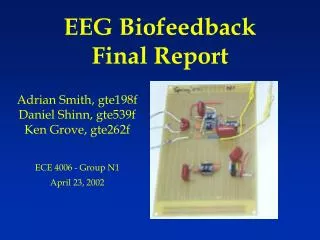
EEG BiofeedbackFinal Report Adrian Smith, gte198f Daniel Shinn, gte539f Ken Grove, gte262f ECE 4006 - Group N1 April 23, 2002
What is an EEG? • EEG stands for electroencephalogram • EEG signals are created by measuring the difference in electrical currents across neuron membranes • Electrodes attached to the body pick up these signals • There can be a only a few electrodes or many attached to the head
EEG signals • Many naturally occurring signals in the human body effect EEG signals • Frequency Analysis helps to separate the different signals
Types of EEG signals • EEG signals have been classified into 4 categories: • Delta 0.3 to 4 Hz • Dreamless sleep • Theta 4 to 8 Hz • Associated with thoughts which produce dreams • Alpha 8 to 13 Hz • Result of unfocused thoughts • Beta above 13 Hz • Result of interactions with environment
Electrode placement • Electrode placement can effect signals received
Related Research • Creating a Brain Computer Interface (BCI) has been a goal for researchers since computers were first introduced • BCI’s could help patients with motor disabilities use computers or mobility platforms • What is necessary: • Amplification • Filtering • Classification • Control
Related Research (cont.) • Large programs researching BCI’s: • Wadsworth Center in Albany • Graz University of Technology in Austria • Problems facing the programs: • Data transfer rate • Efficiency • Differences between test subjects • Learning curve for new users
Previous Semesters Work • Produced an amplifier that can output a strong enough signal to process with an Analog to Digital Converter • Created a baseline for our work with the amplifier and EEG signals
Our Focus • Purchase components needed to replicate the amplifier board • Assemble our amplifier board • Purchase and install an ADC board that can remain with the class for use in future semesters • Digitize the output signal • Interpret signals as commands for controlling a remote control vehicle • Output control commands to remote control vehicle
Amplifier Board • Built in previous semester • Based on Thomas Collura’s design, founder of Brainmaster • Two stage amplifier • 7805 voltage regulator power supply • Can use 9V battery or 6V-35V DC power supply
Stage 1 Gain of 50 Common Mode Rejection Ratio Provides noise reduction and signal centering Stage 2 Gain of 390 Capacitors stabilize power supply Amplifier Design
Resistors: (1) 10K 1/4W 5% (2) 1K 1/4W 5% (3) 130K 1/4W 5% (2) 200K 1/4W 5% (2) 10M 1/4W 5% (2) 200K 1/4W 5% (1) 51K 1/4W 5% Integrated Circuits: (3) OP-90 amplifiers (1) 620AN amplifier (1) LM7805C voltage regulator Capacitors: (1) 0.47uF 400V polypropylene (P474J) (3) 0.1uF 400V polypropylene (P104J) (2) 0.001uF 400V polypropylene (P103J) (1) 10uF 6.3VDC Tantalum Other: (1) Set of 3 conductor signal leads Amplifier Parts List
Analog-Digital Converter • Current board is a Keithley DAS-1701ST • Installed in borrowed computer • Must be moved but face PCI interface problem • Keithley KPCI-1307 card is the proposed solution
Keithley KPCI-1307 • 100k samples/sec • 16 single ended or 8 differential inputs • AutoZero capability filters out drift • 32 digital I/O • 3 clock/timer • drivers included • VHDL program or DriverLINX software options • Price : $680
VHDL Implementation • Download code to Flex10k20 chip on Altera board • Board receives signals from the KPCI-1307 and controls mechanical devices
DriverLINX Implementation • Create DLLs for data acquisition and signal routing • Interface can be programmed in • C • C++ • Visual Basic • Active X
Overview of Completed Objectives • EEG Amplifier • Order parts • Assembly • Testing • Data Acquisition Board • Order board • Installation of board • Installation of drivers and software
EEG Amplifier (Parts) • Resistors: (1) 10K 1/4W 5% (2) 1K 1/4W 5% (3) 130K 1/4W 5% (2) 200K 1/4W 5% (2) 10M 1/4W 5% (2) 200K 1/4W 5% (1) 51K 1/4W 5% • Capacitors: (1) 0.47uF polypropylene (P474J) [$1.62] (3) 0.1uF polypropylene (P104J) [$0.74] (2) 0.001uF polypropylene (P103J) [$0.45] (1) 10uF 6.3VDC Tantalum [$0.52] • Integrated Circuits: (3) OP-90 amplifiers [$2.35] (DIP package was not available when placing orders so SOIC package was substituted with the use of an 8-pin SOIC to DIP adapter. Price reflects cost of DIP package, as this should be ordered in future semesters.) (1) 620AN amplifier [$5.92] (1) LM7805C voltage regulator [$0.43] • Other: (1) Set of 3 conductor signal leads [$14.40] (3) Disposable electrodes for each testing session [$0.24] (1) Pre-holed circuit board [$8.49]
EEG Amp – Assembly and Testing Group N1’s Lab Rat EEG Amp Fully Assembled
Data Acquisition Board - Installation • KPCI-3107 • 16 analog single-ended or 8 analog differential. • 32 digital outputs • PCI interface • CAB-1284CC-2 • STP-36
KPCI-3107 (DriverLINX software) • Real-time data acquisition (with test panels) • Analog/Digital I/O programming • uses C++, VB, and Active X • Real-time Triggering via driver • allows user to specify trigger voltage and action to take after device is triggered.
Final Testing Waveforms AIO Test Panel with Sine Wave input to Channel A • The test panel allowed for verification that the acquisition board was functioning correctly • Eyebrow and eye blinks were recorded and graphed using the A/D board.
Board at End of Semester – A/D Board A/D board connected to Computer Amplifier connected to A/D board with electrodes
Ideas for Continuing the Project • Build a low-noise case for STP-36 break-out boards. • Calibrate gain for the EEG Amp input signal into an analog differential input channel. • Research and learn how to use programming knowledge into a DriverLINX program. • Program driver for KPCI-3107 board to output needed digital signal.