Types of Materials
370 likes | 839 Vues
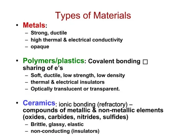
Types of Materials. Metals : Strong, ductile high thermal & electrical conductivity opaque Polymers/plastics : Covalent bonding sharing of e’s Soft, ductile, low strength, low density thermal & electrical insulators Optically translucent or transparent.

Types of Materials
E N D
Presentation Transcript
Types of Materials • Metals: • Strong, ductile • high thermal & electrical conductivity • opaque • Polymers/plastics: Covalent bonding sharing of e’s • Soft, ductile, low strength, low density • thermal & electrical insulators • Optically translucent or transparent. • Ceramics: ionic bonding (refractory) – compounds of metallic & non-metallic elements (oxides, carbides, nitrides, sulfides) • Brittle, glassy, elastic • non-conducting (insulators)
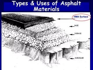
The Materials Selection Process Processes Structure Shape Composition Mechanical Electrical Thermal Optical Etc. Materials Properties Environment Load Applications Functions
Structure, Processing, & Properties (d) 30mm (c) (b) (a) 4mm 30mm 30mm • Properties depend on structure ex: hardness vs structure of steel Steel with 0.4 wt% C d) Martensite c) Martensite (tempered at 371 C) b) Fine pearlite a) Spheroidite 6 00 5 00 4 00 Hardness (BHN) 3 00 2 00 100 0.01 0.1 1 10 100 1000 Cooling Rate (ºC/s) • Processing can change structure ex: structure vs cooling rate of steel
6 5 Cu + 3.32 at%Ni 4 Cu + 2.16 at%Ni Resistivity, r deformed Cu + 1.12 at%Ni 3 (10-8 Ohm-m) 2 Cu + 1.12 at%Ni 1 “Pure” Cu 0 -200 -100 0 T (°C) ELECTRICAL • Electrical Resistivity of Copper: • Adding “impurity” atoms to Cu increases resistivity. • Deforming Cu increases resistivity.
400 300 (W/m-K) 200 Thermal Conductivity 100 0 0 10 20 30 40 Composition (wt% Zinc) 100mm THERMAL • Space Shuttle Tiles: --Silica fiber insulation offers low heat conduction. • Thermal Conductivity of Copper: --It decreases when you add zinc!
Fe+3%Si Fe Magnetization Magnetic Field MAGNETIC • Magnetic Storage: --Recording medium is magnetized by recording head. • Magnetic Permeability vs. Composition: --Adding 3 atomic % Si makes Fe a better recording medium!
OPTICAL polycrystal: low porosity polycrystal: high porosity single crystal • Transmittance: --Aluminum oxide may be transparent, translucent, or opaque depending on the material structure.
-8 10 “as-is” “held at 160ºC for 1 hr crack speed (m/s) before testing” -10 10 Alloy 7178 tested in saturated aqueous NaCl solution at 23ºC increasing load 4mm DETERIORATIVE • Stress & Saltwater... --causes cracks! • Heat treatment: slows crack speed in salt water! --material: 7150-T651 Al "alloy" (Zn,Cu,Mg,Zr)
Properties From Bonding: Tm Energy r r o r Energy smaller Tm unstretched length larger Tm r o r Eo = “bond energy” • Bond length, r • Melting Temperature, Tm • Bond energy, Eo Tm is larger if Eo is larger.
Properties From Bonding : a length, L o unheated, T 1 D L heated, T 2 r o Energy unstretched length r Larger a Eo Eo Smaller a • Coefficient of thermal expansion, a coeff. thermal expansion D L a = ( T - T ) 2 1 L o • a ~ symmetry at ro a is larger if Eo is smaller.
Summary: Primary Bonds secondary bonding Ceramics Large bond energy large Tm large E small a (Ionic & covalent bonding): Metals Variable bond energy moderate Tm moderate E moderate a (Metallic bonding): Polymers Secondary bonding dominates small Tm small E large a (Covalent & Secondary):
The Periodic Table • Columns: Similar Valence Structure H He Li Be O F Ne Na Mg S Cl Ar K Ca Sc Se Kr Rb Sr Y Te I Xe Cs Ba Po At Rn Fr Ra
Energy and Packing Energy typical neighbor bond length typical neighbor r bond energy • Dense, ordered packing Energy typical neighbor bond length r typical neighbor bond energy • Non dense, random packing Dense, ordered packed structures tend to have lower energies.
Materials and Packing Crystalline materials... • atoms pack in periodic, 3D arrays • typical of: -metals -many ceramics -some polymers crystalline SiO2 Si Oxygen Noncrystalline materials... • atoms have no periodic packing • occurs for: -complex structures -rapid cooling "Amorphous" = Noncrystalline noncrystalline SiO2
Types of Imperfections Line defects • Dislocations Area defects • Grain Boundaries • Vacancy atoms • Interstitial atoms • Substitutional atoms Point defects
Point Defects Vacancy distortion of planes self- interstitial distortion of planes • Vacancies: -vacant atomic sites in a structure. • Self-Interstitials: -"extra" atoms positioned between atomic sites.
Point Defects in Alloys Two outcomes if impurity (B) added to host (A): • Solid solution of B in A (i.e., random dist. of point defects) OR Substitutional solid soln. (e.g., Cu in Ni) Interstitial solid soln. (e.g., C in Fe) • Solid solution of B in A plus a new phase (usually for a larger amount of B) Second phase particle --different composition --often different structure.
Line Defects Dislocations: • are line defects, • slip between crystal planes result when dislocations move, • produce permanent (plastic) deformation. Schematic of Zinc (HCP): • before deformation • after tensile elongation slip steps
Imperfections in Solids Edge Dislocation
Imperfections in Solids Screw Dislocation Screw Dislocation b Dislocation line (b) Burgers vector b (a)
Mixed Edge Screw Edge, Screw, and Mixed Dislocations
Dislocations & Crystal Structures • Structure: close-packed planes & directions are preferred. view onto two close-packed planes. close-packed directions close-packed plane (bottom) close-packed plane (top) • Comparison among crystal structures: HCP: few slip systems/directions; FCC: many slip systems/directions; BCC: the most slip systems/directions • Specimens that were tensile tested. Mg (HCP) tensile direction Al (FCC)
Planar Defects in Solids • External Surfaces • The most obvious • Grain Boundary • Different crystal • orientation between • grains • twin boundary (plane) • Essentially a reflection of atom positions across the twin plane. • Stacking faults • For FCC metals an error in ABCABC packing sequence • Ex: ABCABABC • Phase boundary • In multiphase materials
Polycrystalline Materials Grain Boundaries • regions between crystals • transition from lattice of one region to that of the other • slightly disordered • low density in grain boundaries • high mobility • high diffusivity • high chemical reactivity