Multi- and Hyperspectral Remote Sensing
830 likes | 1.6k Vues
Multi- and Hyperspectral Remote Sensing. Multi- vs. Hyperspectral RS. Multi- and Hyperspectral RS Collection of reflected, emitted, or backscattered energy from an object or area in multiple regions of the EM spectrum Typically collection of energy in digital format Multispectral:

Multi- and Hyperspectral Remote Sensing
E N D
Presentation Transcript
Multi- and Hyperspectral Remote Sensing
Multi- vs. Hyperspectral RS • Multi- and Hyperspectral RS • Collection of reflected, emitted, or backscattered energy from an object or area in multiple regions of the EM spectrum • Typically collection of energy in digital format • Multispectral: • Multiple (a few; > 2), wide, separated wavelength bands • Hyperspectral: • Multiple (hundreds), narrow, contiguous wavelength bands • Major difference: • Not so much the number of measured wavelengths but the narrowness and contiguous nature of the measurements
Multi- vs. Hyperspectral RS • Spectral profiles for tumbleweed (USGS) Green – Hyperspectral Red – Multispectral (Landsat 7 ETM+)
Multi- vs. Hyperspectral RS • Spectral Resampling
Data Collection • Detection of EM energy from AOI at sensor • Recording of energy as analog electrical signal • Onboard conversion of analog electric signal into digital value through analog-to-digital (A-to-D) conversion • Aircraft platform: digital data “flown” back to Earth • Satellite platform: digital data “telemetered” to Earth receiving stations directly or indirectly via tracking and data relay satellites (TDRS) • Ground: • Data preprocessing • Information extraction • Distribution and use
Digital Image Terminology • Pixel • 2D picture element that is the smallest non-divisible element of a digital image • Digital RS data are stored as a matrix (array) of digital numbers, whereby each pixel has a location value (row i and column j) in the matrix and a brightness value (BV) for each of the individual spectral bands (k) BVi, j, k • n spectral bands are registered to one another • i and j for a pixel are the same in all bands; only a pixel’s BV may/should vary from band to band
Digital Image Terminology • BV range (quantization level of sensor system) • 8 bits BVs range from 0 to 255 • 12 bits BVs range from 0 to 1023 • The more bits, the more precise the measurement of radiance
Detection & Recording of EM Energy • The Basics • Most RS instruments (sensors) measure photons • Photoelectric effect at the detector • Electrons (negatively charged particles) are emitted when a negatively charged, light-sensitive plate (detector) is subjected to a beam of photons • Emitted electrons (numbers, intensity) can be collected and counted as a signal • Magnitude of electric current (number of photoelectrons per unit time) is proportional to light intensity • Kinetic energy of released photoelectrons varies with wavelength of the impinging radiation • Note: detector material determines the EM wavelengths over which the detector will operate (e.g., silicon for visible light)
Spatial information Imagers Altimeters Sounders Imaging Radiometer Imaging Spectrometer Polarimeters Scatterometers Radiometers Spectro-Radiometer Spectrometers Intensity information Spectral information Sensor Classes • Sensor classes according to principle parameter measured • Passive Sensors: • Radiometers • Spectrometers • Spectro-radiometers • Imager • Polarimeter • Sounders • Active Sensors: • Radars • Lidars • Scatterometers • Altimeters • Sounders
Sensor Classes – Passive • Radiometer • Instrument that quantitatively measures the intensity of EM radiation in some interval of the EM spectrum • Spectrometer • Device that detects, measures, and analyzes the spectral content of incident EM radiation • Has a dispersing element (e.g., prism) that breaks radiation extending over part of the spectrum into discrete wavelengths and disperses them at different angles to detectors • Spectro-radiometer • Radiometer that measures the intensity of EM radiation in multiple spectral bands rather than at discrete wavelengths
Sensor Classes – Passive • Imager • Device that detects EM radiation with spatial resolution (e.g., CCD); scans either mechanically or electronically • Polarimeter • Instrument that measures the state of polarization (related to vibration of EM waves) of EM radiation • Sounder (passive and active) • Instrument that measures vertical distributions of atmospheric parameters (e.g., temperature) from multispectral information
Sensor Classes – Active • RADAR • Active Radio Detection and Ranging sensor • Provides its own source of EM energy (i.e., emits microwave radiation) • Detects, measures, and times the backscattered microwave radiation • LIDAR • Light Detection and Ranging sensor • Uses a laser (light amplification by stimulated emission of radiation) to transmit a pulse and a receiver with sensitive detectors to measure the backscattered or reflected light
Sensor Classes – Active • Scatterometer • High-frequency microwave radar designed specifically to measure backscattered radiation • Altimeter • Instrument that measures the height of the platform (aircraft, spacecraft) above the surface
non-scanning imaging Passive Image plane scanning scanning imaging Object plane scanning non-imaging non-scanning imaging Active Image plane scanning scanning imaging Object plane scanning Sensor Types non-imaging Sensor Type
Passive vs. Active Sensors • Passive Sensors • Detect EM radiation that is naturally reflected or emitted by objects (energy source: sun) • Active Sensors • Detect EM radiation that is reflected from objects that are irradiated from artificially generated energy sources (e.g., radar, lidar)
Scanning vs. Non-Scanning • Scanning System • System that senses a scene point by point (e.g., small areas within the scene) along successive lines over a finite time • Involves movement of either the entire sensor or of one or more of its components • Non-Scanning System (~ Framing system) • Sensors that either don’t sweep (e.g., laser) or that produce an image instantaneously (e.g., camera, eye, TV)
Imaging vs. Non-Imaging • Imaging • System that measures the intensity of radiation as a function of position on the Earth’s surface so that a 2D-image of radiation intensity can be generated (e.g., cameras, scanners) • Non-Imaging • Either does not measure the intensity of radiation OR does not do so as a function of position on the Earth’s surface (average of signal strength, etc.; 1D)
Scanning, Imaging Systems • Sensors that sweep (mechanically or electronically) over terrain to produce an image Two broad categories: • Optical-mechanical: • contains essential mechanical component (e.g., moving mirror) that aids in scene scanning • Optical-electronic: • sensed radiation moves directly through the optics onto the linear or array detectors
Scanning, Imaging Systems • Object plane scanner (~ Optical-mechanical): • Images one target pixel at-a-time, and all pixels in a sequential fashion, from the object plane to the image plane • Scanning mechanism (e.g., mirror) “points” the scanner to different target pixels in a sequential fashion • Image plane scanner (~ Optical-electronic): • Images an entire scan line or frame at-a-time on the image plane • Scanning takes place on the image plane • Has larger array of detectors in the image plane than an object plane scanner
Scanning, Imaging Systems Image plane scanner Object plane scanner
Passive Sensor Types • Passive, non-scanning, non-imaging • Microwave radiometer, magnetic sensor, gravimeter, Fourier spectrometer, etc. • Passive, non-scanning, imaging • Camera: monochrome, natural color, infrared, color infrared, etc. • Passive, scanning, imaging, image plane scanning • TV camera, etc. • Passive, scanning, imaging, object plane scanning • Optical-mechanical scanner, microwave radiometer
Active Sensor Types • Active, non-scanning, non-imaging • Microwave radiometer, microwave altimeter, laser water depth meter, laser distance meter • Active, scanning, imaging, image plane scanning • Passive phase array radar • Active, scanning, imaging, object plane scanning • Real aperture radar, synthetic aperture radar
Motion of Sensors • Two types of forward-moving scanners: • Cross-Track Scanners • Along-Track Scanners • Orbit or Flight path • Forward-moving track • Swath width • Area monitored from side to side of path
Sensor Types • Cross-Track Scanners • Use a rotating (spinning) or oscillating mirror to sweep along a line (long and narrow) or a series of adjacent lines traversing the ground • Optical-mechanical • Whiskbroom
Sensor Types • Along-Track Scanners • Use a line of detectors (charged-coupled devices, CCDs) – as platform advances along the track, radiation is received simultaneously at all detectors • Optical-electronic • Pushbroom
Sensor Types • Discrete detector • Have a single active area • Linear arrays • Have a few to several thousand detectors lined up in a row • Area arrays • Have two-dimensional area arrays
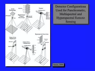
Sensor Type I • Analog Frame Camera and Film • Acquires traditional aerial photography • Film with silver halide crystals (emulsion) instead of detectors
Sensor Type II • Digital Frame Camera Area Array • Each spectral band has a filter and a separate area array • Number of detectors = # of rows # of columns # of bands Light B3 Each one of these is a single detector. B2 B1
Sensor Type III • Linear Array (“Pushbroom”) • Similar to area array, but has only 1 row (line) of detectors • Array is moved in a single direction, and a radiance reading is taken at regular intervals • 1 linear array per spectral band; number of pixels contained in one row of an image equals the number of detectors • Filters are used to restrict the wavelengths IFOV (1 detector) Linear array Objective lens Angular field of view Sensor movement direction • Pixel width = easily calculated • Pixel length = function of IFOV, sensor speed and detector sampling.
Sensor Type IV • Scanning Mirror and Single Discrete Detectors (“Whiskbroom”) and Filters • 1 detector per spectral band • Rotating mirror changes the angle of the incident light source (hence what portion of the ground is being detected) • Filters restrict the wavelengths for each band Rotating mirror Swath width Detector Angular field of view • Pixel width = function of mirror rotation rate and IFOV • Pixel length = function of IFOV, sensor speed and detector sampling rate Direction of sensor movement
Sensor Type V • Scanning Mirror and Multiple Discrete Detectors (“Whiskbroom”) and Filters • Linear array of detectors for each spectral band • Mirror angles the light across multiple detectors instead of one • Filters restrict the wavelengths for each band Pushbroom sensors: may have thousands of detectors per spectral band Scanning mirror sensors: usually only have a few detectors per spectral band (e.g., if there are 6 detectors per array, every 6th pixel in the image is from a given detector) MSS scanning arrangement
Sensor Type VI • Scanning Mirror and Multiple Discrete Detectors (“Whiskbroom”) and Dispersing Element • Instead of wide band filters, this type has a dispersing element (prism) that breaks the incoming radiation into discrete wavelengths and disperses it across a linear array of detectors • Rotating mirror and forward sensor movement create the spatial arrangement of pixels Advantage of dispersing element (vs. a set of filters): much smaller bands can be detected without a massive amount of additional hardware (there is not 1 filter per band as in the previous sensors)
Sensor Type VI • Hyperspectral Area Array • Combines pushbroom linear array with a dispersing element
Data Transmission • All sensors record the image data digitally • Data must routinely be transmitted to Earth • Memory buffer (Think about your “hard drive” …) may fill up • We want to use it (Data doesn’t do us any good in orbit.)
Sensor Movement • All detector configurations require forward movement of the detectors to create an image • Two exceptions: • Digital frame camera area arrays • Stationary platforms • Satellites and airplanes are ideal platforms on which to mount sensors
Sensor Movement • Polar-orbiting satellites • Orbit in north-south direction while Earth spins beneath it in east-west direction Satellites can scan the entire Earth’s surface (like pealing an orange around and around, one strip at a time) • Relatively low altitude: 300–800 km above the surface • Must move quickly to avoid being pulled in by Earth’s gravitational field • Circle approximately every 90 minutes
Sensor Movement • Geosynchronous-orbiting satellites • Orbit roughly at the speed of Earth’s rotation Satellites are always above the same spot and scan the same region • Relatively high altitude: 36,000 km above the surface • Monitor almost one-third of the Earth’s surface and have full-disk view of the Earth from pole to pole
Sensor Movement • Geostationary-orbiting satellites • Appear to remain in the same position above the Earth • Circular orbit with an inclination of zero degrees (i.e., above the equator) • Altitude: ca. 36,000 km • Speed: 3 km/sec • Orbital period: ca. 24 hours • Called geostationary because they appears to be stationary when viewed from Earth • Typical roles: weather observation and broadcasting
Sensor Movement • Geostationary-orbiting satellites
Sensor Movement • Synchronous-orbiting satellites • Hoe around the Earth once per day and return to their original positions • Circular or elliptical orbit with varying inclinations • Orbital period: 24 hours • Typical role: monitoring of, and providing communications for, areas in higher latitudes
Sensor Movement • Recurrent-orbiting satellites • Return to their starting points above Earth’s surface within one day, regardless of how many orbits they have made in that time overall • Circular or elliptical orbits • Orbital period: integral fraction of Earth’s rotation period • Typical roles: communications and observation functions over higher altitudes
Sensor Movement • Sub-recurrent-orbiting satellites • Orbit the Earth several times per day but return to their starting points above Earth’s surface a number of days later, at the same time of day • Orbital period: satellite that returns to starting point above Earth’s surface after 16 days would have a 1 16-day sub-recurrent orbit • Typical roles: long-term, regular monitoring of the Earth’s surface
Sensor Movement • Sun-synchronous-orbiting satellites • Orbital plane and Sun’s direction are always the same • Direction of rotation of the orbital plane and the period (rotation angle per day) are the same as the Earth’s orbital period (rotation angle per day) • Looking at the Earth from an orbiting satellite, the Sun’s radiation would always be coming from the same angle • Orbital inclinations and altitude must be in tune to generate a sun-synchronous orbit • Orbital period: one year • Typical roles: monitoring of sites that must always be observed under the “same” conditions
Sensor Movement • Sun-synchronous-orbiting satellites
Sensor Movement • Sun-synchronous-sub-recurrent-orbiting satellites • Combines sun-synchronous orbit with a sub-recurrent orbit • Orbital period: once every few days • Typical roles: Earth observation --- global coverage yet relatively frequent coverage of same broad regions of the Earth’s surface
Sensor Movement • Example: Landsat 1-3 • Sun-synchronous, circular orbit • Nominal altitude: 919 km • Orbital inclination: 99º (nearly polar; crosses equator at 9º) • 1 orbit/103 min. 14 orbits/day • Position below spacecraft moves: 2,875 km/orbit 40, 250 km/day • Orbit 15 is displaced from orbit 1 at equator by 159 km 18 days later, orbit 252 falls directly over orbit 1 ~ 26 km of overlap between successive orbits • Path & Row World Reference System (WRS) 57,784 scenes each 185 km wide and 170km long