Download
1 / 23
240 likes | 523 Vues
EET 1131 Unit 11 Counter Circuits. Read Kleitz , Chapter 12, skipping Sections 12-10 and 12-11. Homework #11 and Lab #11 due next week. Quiz next week. Counting in Binary.

E N D
EET 1131 Unit 11Counter Circuits • Read Kleitz, Chapter 12, skipping Sections 12-10 and 12-11. • Homework #11 and Lab #11 due next week. • Quiz next week.
Counting in Binary As you know, the binary count sequence follows a familiar pattern of 0’s and 1’s as described in Section 2-2 of the text. 0 0 0 0 0 1 0 1 0 0 1 1 1 0 0 1 0 1 1 1 0 1 1 1 LSB changes on every number. The next bit changes on every other number. The next bit changes on every fourth number.
Counting in Binary A counter can form the same pattern of 0’s and 1’s with logic levels. The first stage in the counter represents the least significant bit – notice that these waveforms follow the same pattern as counting in binary. LSB MSB
Synchronous versus Asynchronous The synchronous/asynchronous distinction has different meanings: As applied to inputs: A change on a synchronous input doesn’t affect the outputs until the next active clock edge, but a change on an asynchronous input affects the outputs immediately. As applied to counters: in a synchronous counter, the outputs can all change at the same instant; but in an asynchronous counter, there’s a brief delay between the changing of the outputs.
HIGH Q0 Q1 Q2 J0 J1 J2 CLK C C C Q0 Q1 K0 K1 K2 Three bit Asynchronous Counter In an asynchronous counter, the clock is applied only to the first stage. Subsequent stages derive the clock from the previous stage. The asynchronous counter shown is a three-bit counter (also called MOD-8 counter or divide-by-8 counter). It uses J-K flip-flops in the toggle mode. Waveforms are on the following slide…
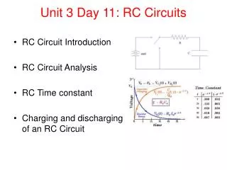
Three bit Asynchronous Counter Notice that the Q0 output is triggered on the rising edge of the clock signal. The following stage is triggered from Q0. The rising edge of Q0 is equivalent to the falling edge of Q0. The resulting sequence is that of a 3-bit binary up counter. CLK Q0 Q1 Q2
Propagation Delay Asynchronous counters are sometimes called ripple counters, because the stages do not all change together. For certain applications requiring high clock rates, this is a major disadvantage. Notice how delays are cumulative as each stage in a counter is clocked later than the previous stage. CLK Q0 Q1 Q2 Q0 is delayed by 1 propagation delay, Q1 by 2 delays and Q2 by 3 delays.
HIGH Q3 Q0 Q1 Q2 J0 J1 J2 J3 CLK C C C C K0 K1 K2 K3 Asynchronous Decade Counter This counter uses a NAND gate to recycle the count sequence to zero after the 1001 state, resulting in a MOD-10 counter (or decade counter). Other truncated sequences can be obtained using a similar technique. CLR Waveforms are on the following slide…
Asynchronous Decade Counter When Q1 and Q3 are HIGH together, the counter is cleared by a “glitch” on the CLR line. CLK Q0 Glitch Q1 Q2 Q3 CLR Glitch
The 74LS93 Asynchronous Counter The 74LS93 has one independent toggle J-K flip-flop driven by CLK A and three toggle J-K flip-flops that form an asynchronous counter driven by CLK B. The counter can be extended to form a 4-bit counter by connecting Q0 to the CLK B input. Two inputs are provided that clear the count. CLK B J0 J1 J2 J3 C C C C CLK A K0 K1 K2 K3 All J and K inputs are connected internally HIGH RO (1) RO (2) Q3 Q0 Q1 Q2
Some Asynchronous Counter ICs • 7490Four bit decade counter (MOD 10) • 7492 Four bit divide-by-12 counter (MOD 12) • 7493 Four bit binary counter (MOD 16)
BCD Decoder/Driver A special-purpose decoder is the 7447. This is a BCD-to-seven segment display with active LOW outputs. VCC BCD/7-seg The a-g outputs are designed for much higher current than most devices (hence the word driver in the name). BI/RBO BI/RBO BCD inputs Outputs to seven segment device LT LT RBI RBI 74LS47 GND
BCD Decoder/Driver Here the 7447 is an connected to an LED seven segment display. Notice the current limiting resistors, required to prevent overdriving the LED display.
7447 BCD-to-7-Segment Decoder/Driver • 4 input pins for BCD code. • 7 output pins to control the seven segments of a 7-segement display. • Also has a lamp test input. • Also a ripple-blanking input and output to suppress leading or trailing zeroes. • Data sheet: 7447
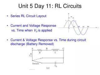
Synchronous Counters In a synchronous counter all flip-flops are clocked together with a common clock pulse. Synchronous counters overcome the disadvantage of accumulated propagation delays, but generally they require more circuitry to control states changes. This 3-bit binary synchronous counter has the same count sequence as the 3-bit asynchronous counter shown previously. HIGH Q0 Q0Q1 Q0 Q1 Q2 J0 J1 J2 C C C K0 K1 K2 CLK
A 4-bit Synchronous Binary Counter The 74LS163 is a 4-bit IC synchronous counter with additional features over a basic counter. It has parallel load, a CLR input, two chip enables, and a ripple count output that signals when the count has reached the terminal count. Data inputs D0 D1 D2 D3 CLR LOAD ENT RCO ENP CLK Example waveforms are on the next slide… Q0 Q1 Q2 Q3 Data outputs
CLR LOAD D0 D1 Data inputs D2 D3 CLK ENP ENT Q0 Q1 Data outputs Q2 Q3 RCO 12 13 14 15 0 1 2 Count Inhibit Clear Preset
Some Synchronous Counter ICs • 74160 and 74162Four bit decade counters (MOD 10) • 74161 and 74163 Four bit binary counters (MOD 16)
D0 D1 D2 D3 Data inputs 74HC190 The 74HC190 is a high speed CMOS synchronous up/down decade (MOD-10) counter with parallel load capability. It also has a active LOW ripple clock output (RCO) and a MAX/MIN output when the terminal count is reached. MAX/MIN CTR DIV 10 RCO C CLK CTEN CTEN LOAD LOAD Q0 Q1 Q2 Q3 Data outputs D0 D1 D2 D3 Data inputs D/U D/U 74HC191 MAX/MIN CTR DIV 16 RCO C CLK Q0 Q1 Q2 Q3 Data outputs Up/Down Synchronous Counters The 74HC191 has the same inputs and outputs but is a synchronous up/down binary(MOD-16) counter.
Some Up/Down Synchronous Counter ICs • 74190Four bit up/down decade counter (MOD 10) • 74191 Four bit up/down binary counter (MOD 16)
Cascading Counters Most counter chips are 4-bit counters, with a modulus of 16 or less. To get larger moduli, you cascade two or more counter chips together. When you cascade counters, their moduli multiply, not add. Example: If you cascade a MOD-10 counter with a MOD-16 counter, you get a MOD-160 counter. The connections for cascading counters differ depending on whether the counters are asynchronous or synchronous.
HIGH Counter 2 Counter 1 CTEN TC CTEN TC CTR DIV 16 CTR DIV 16 CLK C Q2 Q0 Q1 Q3 C Q2 Q0 Q1 Q3 fin Cascaded synchronous counters For synchronous IC counters, the next counter is enabled only when the terminal count of the previous stage is reached. fout • What is the modulus of the cascaded DIV 16 counters? • If fin =100 kHz, what is fout? Example Solution a) Each counter divides the frequency by 16. Thus the modulus is 162 = 256. b) The output frequency is 100 kHz/256 = 391 Hz