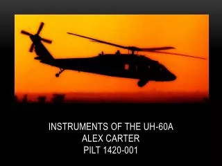
UH-60A/L Fuel System
160 likes | 670 Vues
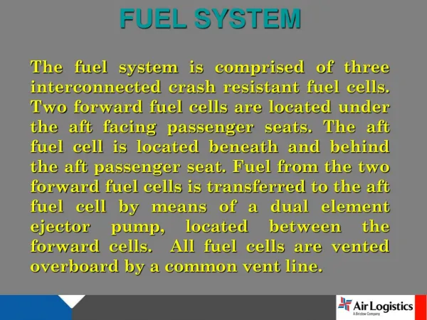
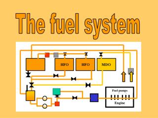
UH-60A/L Fuel System. Components. Main Fuel Cell (2x) Fuel Lines Fuel Selectors Fuel Cell Boost Pump (2x) Prime Boost Pump 30 Micron Fuel Filter (2x) Engine Driven Fuel Pump (2x) Hydromechanical Unit (2x) POU/ODV Oil Cooler (2x). Fuel Cell.

UH-60A/L Fuel System
E N D
Presentation Transcript
Components • Main Fuel Cell (2x) • Fuel Lines • Fuel Selectors • Fuel Cell Boost Pump (2x) • Prime Boost Pump • 30 Micron Fuel Filter (2x) • Engine Driven Fuel Pump (2x) • Hydromechanical Unit (2x) • POU/ODV • Oil Cooler (2x)
Fuel Cell • 181 Gallon Capacity Ballistic Tolerant Self-Sealing Rubber Compound W/Nylon Filament • High-Level Shut-Off Valve • Low-Level Shut-Off Valve • Pressure Refuel/de-fuel Valve • Fuel Quantity & Low Level Sensor • Cell Vents
Fuel Lines • The fuel lines are self-sealing, and have self-sealing, breakaway-type valves. These prevent the loss of fuel in the event of a crash or if the lines are severed. • Check valves to prevent loss of engine prime. • Fuel selector valves.
Fuel Selectors • Two fuel selectors in the engine control quadrant • Connected by low friction push-pull cables • Off, dir(direct), XFD (cross-feed) positions • Fuel from no. 1 tank to no. 1 engine • Fuel from no. 2 tank to no. 2 engine • Fuel from either tank to supply both engines • Fuel from either tank to supply opposite engine.
Fuel Boost Pump • Electrically-operated submerged • Provide pressurized fuel to the engine fuel inlet port • Two position switch • Pressure activated pump-on advisory light(25 psi) • Check valve to prevent loss of engine prime
Prime Boost Pump • Located in front of the no 1 fuel cell component plate. • Controlled by the PRIME BOOST PUMP switch on the upper console. • 5 psi rated output.
Fuel Filter • 30 micron replaceable filter • Impending bypass indicator (LRB)
Engine Driven Boost Pump • Mounted on the Engine Accessory Module. • Negative (suction) 6-8 psi. • Positive 45-90 psi output.
Hydromechanical Unit • Main Fuel Control Device. • Mounted on the rear of the engine accessory gear box. • Contains high pressure (832 psi) pump to deliver fuel to POU/ODV. • Also controls Inlet Guide Vanes and engine Anti-Ice/Start Bleed Valve
POU • On the left aft side of the engine accessory module • Fuel to primer nozzles and main fuel injectors for engine start and operation • Purges fuel from primer nozzles • Drains main fuel manifold • Reduces fuel flow to prevent engine overspeed ODV • The ODV replaces the POU with the same functions, in addion: • Sends fuel through the main fuel manifold to the injectors • Shuts off fuel flow to prevent an overspeed condition • Shuts off fuel to prevent a hot start • Purges fuel injectors on shutdown
Oil Cooler • The Oil Cooler is a heat exchange unit that cools engine oil and pre-heats the fuel for better atomization the ensure proper ignition and burn.
L Model • Hot Start Prevention • Np Overspeed Protection System • Fuel Burn Rates
Summary • Components • A Model/ L Model differences