Download
1 / 34
340 likes | 475 Vues
FY 2002 Initiative IV&V of UML. Less risk, sooner - A Catch Phrase by Coach Menzies WVU UI: Architectural-level Risk Assessment. Hany Ammar, Katerina Goseva-Popstojanova, V. Cortelessa, Ajith Guedem, Diaa Eldin Nassar, Walid AbdelMoez, Ahmad Hassan, and Rania Elnaggar

E N D
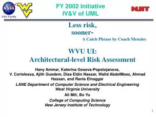
FY 2002 Initiative IV&V of UML Less risk, sooner- A Catch Phrase by Coach Menzies WVU UI: Architectural-level Risk Assessment Hany Ammar, Katerina Goseva-Popstojanova,V. Cortelessa, Ajith Guedem, Diaa Eldin Nassar, Walid AbdelMoez, Ahmad Hassan, and Rania Elnaggar LANE Department of Computer Science and Electrical EngineeringWest Virginia University Ali Mili, Bo Yu College of Computing ScienceNew Jersey Institute of Technology
Outline • Objectives • What we can do • Why UML • UML & NASA • Project Overview • Architecture-Based Risk Analysis • The Risk Assessment Methodology • Performance – based risk • Accomplishments • Future Work • Publications
Objectives • Automated techniques V&V of dynamic specifications • Performance and timing analysis • Fault-injection based analysis, • Less risk, sooner • Risk assessment • Technologies: • UML • Architectures • Risk assessment methodology • Benefits: • Find & rank critical • use cases, scenarios, • components, connectors Before bad software After bad software The ARIANE 5explosion
What We Can Do Not contributing Minor Major Critical Catastrophic • Identify and rank critical components based on risk factors and severity classes • How?- details follow
Why UML • Unified modeling language • Rational software • The three amigos: Booch Rumbaugh, Jacobson. • International standard in system specification An international standard In system specification
UML & NASA • Increasing use at NASA • Informal (very) survey • Google search: • “rational rose nasa” • 10,000 hits • 3 definite projects, just in first ten • We use a case study based on the UML specs of a component of the International Space Station
Project Overview FY01 • Developed of an automated simulation environment for UML dynamic specification, suggested an observer component to detect errors • Conducted performance and timing analysis of the NASA case study FY02 • Develop a fault injection methodology Define a fault-model for components at the specification level • Develop a methodology for architecture-based risk analysis Determine critical use case List Determine critical component/connector list (based on recent paper by Yacoub & Ammar on IEEE Trans. on Software Engineering, June 02) FY03 • Develop a methodology for performance-based/reliability-based risk assessment • Validation of the risk analysis methodology on several NASA projects
Architecture-Based Risk Analysis • Develop architecture-based approach for risk assessment • Overall system/subsystem • Different use cases • Key scenarios associated with use cases • Heavily used scenarios • Scenarios that are used infrequently but perform critical functions • Develop components and connectors risk factors • Define components risk factors as Normalized dynamic complexity * Severity • Estimate dynamic complexity measure based UML sequence diagrams and state charts • Estimate severity measure based FEMA and hazard analysis • Consistent with the NASA definition of risk Probabilityof an undesired event * Consequences if that event should occur • Define connectors risk factor as Normalized dynamic coupling * Severity
Risk Assessment Methodology • For each use case • For each scenario • For each component • Measure dynamic complexity • Assign severity based on FMEA and hazard analysis • Calculate risk factor • For each connector • Measure dynamic coupling • Assign severity based on FEMA and hazard analysis • Calculate risk factor • Construct Markov model • Calculate scenario level risk factor • Determine critical component/connector list • Calculate use case level risk factors • Rank the scenarios based on risk factors, Determine critical scenarios list • Calculate system level risk • Rank the use cases based on risk factors, Determine critical use case list • Determine critical component / connector list in the system scope
Risk Assessment Methodology • For each use case • For each scenario • For each component • Measure dynamic complexity • Assign severity based on FMEA and hazard analysis • Calculate risk factor • For each connector • Measure dynamic coupling • Assign severity based on FEMA and hazard analysis • Calculate risk factor • Construct Markov model • Calculate scenario level risk factor • Determine critical component/connector list • Calculate use case level risk factors • Rank the scenarios based on risk factors, Determine critical scenarios list • Calculate system level risk • Rank the use cases based on risk factors, Determine critical use case list • Determine critical component / connector list in the system scope
Risk Assessment Methodology • For each use case • For each scenario • For each component • Measure dynamic complexity • Assign severity based on FMEA and hazard analysis • Calculate risk factor • For each connector • Measure dynamic coupling • Assign severity based on FEMA and hazard analysis • Calculate risk factor • Construct Markov model • Calculate scenario level risk factor • Determine critical component/connector list • Calculate use case level risk factors • Rank the scenarios based on risk factors, Determine critical scenarios list • Calculate system level risk • Rank the use cases based on risk factors, Determine critical use case list • Determine critical component / connector list in the system scope
Risk Assessment Methodology • For each use case • For each scenario • For each component • Measure dynamic complexity • Assign severity based on FMEA and hazard analysis • Calculate risk factor • For each connector • Measure dynamic coupling • Assign severity based on FEMA and hazard analysis • Calculate risk factor • Construct Markov model • Calculate scenario level risk factor • Determine critical component/connector list • Calculate use case level risk factors • Rank the scenarios based on risk factors, Determine critical scenarios list • Calculate system level risk • Rank the use cases based on risk factors, Determine critical use case list • Determine critical component / connector list in the system scope
Component Dynamic Complexity Dynamic Complexity of a component Oi in scenario x is defined as : Where CCx(oi ) =ti – ci + 2 Is the cyclomatic complexity of a component Oi in scenario x Cx(oi ) : A finite set of states for a component Oifor a scenario x,ciis the cardinality of this set. Tx(oi ) : A finite set of transitions from one state to another for Oicomponent in a scenario x, ti is the cardinality of this set. Ox : is the set of components collaborating during the execution of a scenario
Risk Assessment Methodology • For each use case • For each scenario • For each component • Measure dynamic complexity • Assign severity based on FMEA and hazard analysis • Calculate risk factor • For each connector • Measure dynamic coupling • Assign severity based on FEMA and hazard analysis • Calculate risk factor • Construct Markov model • Calculate scenario level risk factor • Determine critical component/connector list • Calculate use case level risk factors • Rank the scenarios based on risk factors, Determine critical scenarios list • Calculate system level risk • Rank the use cases based on risk factors, Determine critical use case list • Determine critical component / connector list in the system scope
Connector Dynamic Coupling • Dynamic couplingfor connector between component Oi and componentOj is the percentage of the number of messages sent from Oi to OJ with respect to the total number of messages exchanged during the scenario x MTx(Oi ,Oj) : is the set of messages sent from component Oi to component Oj during the execution of scenario x MTx : is the set of total messages exchanged between all components during the execution of scenario x.
Connector Dynamic Coupling • Dynamic Couplingfor Connector between component C1and component C2 is EOC(C1,C2) =2/5=0.4 M1 M2 M3 M4 M5 C2 C3 C1
Risk Assessment Methodology • For each use case • For each scenario • For each component • Measure dynamic complexity • Assign severity based on FMEA and hazard analysis • Calculate risk factor • For each connector • Measure dynamic coupling • Assign severity based on FEMA and hazard analysis • Calculate risk factor • Construct Markov model • Calculate scenario level risk factor • Determine critical component/connector list • Calculate use case level risk factors • Rank the scenarios based on risk factors, Determine critical scenarios list • Calculate system level risk • Rank the use cases based on risk factors, Determine critical use case list • Determine critical component / connector list in the system scope
PFMC_MT S RPCM_MT Minor PFMC_LT Major FRITCS Critical SCITCS RPCM_LT T Catastrophic The Markov Chain Model forBoth Pumps Retry- scenario FAILURE STATES OF VARIOUS SEVERITIES
Risk Assessment Methodology • For each use case • For each scenario • For each component • Measure dynamic complexity • Assign severity based on FMEA and hazard analysis • Calculate risk factor • For each connector • Measure dynamic coupling • Assign severity based on FEMA and hazard analysis • Calculate risk factor • Construct Markov model • Calculate scenario level risk factor • Determine critical component/connector list • Calculate use case level risk factors • Rank the scenarios based on risk factors, Determine critical scenarios list • Calculate system level risk • Rank the use cases based on risk factors, Determine critical use case list • Determine critical component / connector list in the system scope
Distribution of risk factors of each scenario over the severity classes
Risk Assessment Methodology • For each use case • For each scenario • For each component • Measure dynamic complexity • Assign severity based on FMEA and hazard analysis • Calculate risk factor • For each connector • Measure dynamic coupling • Assign severity based on FEMA and hazard analysis • Calculate risk factor • Construct Markov model • Calculate scenario level risk factor • Determine critical component/connector list • Calculate use case level risk factors • Rank the scenarios based on risk factors, Determine critical scenarios list • Calculate system level risk • Rank the use cases based on risk factors, Determine critical use case list • Determine critical component / connector list in the system scope
Overall System risk distribution over the severity classes The overall system risk factor is: 0.8189
Risk Assessment Methodology • For each use case • For each scenario • For each component • Measure dynamic complexity • Assign severity based on FMEA and hazard analysis • Calculate risk factor • For each connector • Measure dynamic coupling • Assign severity based on FEMA and hazard analysis • Calculate risk factor • Construct Markov model • Calculate scenario level risk factor • Determine critical component/connector list • Calculate use case level risk factors • Rank the scenarios based on risk factors, Determine critical scenarios list • Calculate system level risk • Rank the use cases based on risk factors, Determine critical use case list • Determine critical component / connector list in the system scope
Determine Critical Component/Connector List Not contributing Minor Major Critical Catastrophic
X1 X2 X3 T11 T21 D21 T22 D22 T31 D31 D11 = is demand for resource T23 D23 (e.g, CPU, disk, etc.) in state Tij (state j of component i ) T32 D32 T12 D12 Scaling vector scales the resource demands accordingly to the corresponding service times of the resources Performance – based risk • Performance failure is the inability of the system to meet its performance objective(s) • Define components performance-based risk as • Normalized component demand factor * Severity
Total demand of component xi in a scenario Sk is • Overall demand of a scenario Sk is • Normalized demand factor of componentxiin ScenarioSk • DFi = ( . SCT)/ ( . SCT) Performance – based risk where m is total number of components and l total number of states for a given component in a given scenario
Accomplishments • Developed analytical techniques and a methodology for Architecture-Based Risk Analysis • A lightweight approach based on static analysis of dynamic specifications is developed and automated • A tool will be presented in the Tools session • Applied the methodology and tool to the NASA case study
Future Work • The main thrust of our future work will be in the development of a cohesive methodology for performance- based /reliability- based risk assessment • Compare risk factors based on other Complexity and coupling metrics obtained from static analysis of UML dynamic specs. • COSMIC-Full Function Point measurement maybe a good complexity predictor. • COCOMO II’s effort prediction may be another good complexity predictor • Validation of methodology using several NASA case studies
Publications • Sherif M. Yacoub, Hany H. Ammar , “A Methodology for Architecture-Level Reliability Risk Analysis,” IEEE Transactions on Software Engineering, June 2002, pp. 529-547 • H. H. Ammar, T. Nikzadeh, and J. B. Dugan "Risk Assessment of Software Systems Specifications," IEEE Transactions on Reliability, September 2001 • Hany H. Ammar, Sherif M. Yacoub, Alaa Ibrahim, “A Fault Model for Fault Injection Analysis of Dynamic UML Specifications,” International Symposium on software Reliability Engineering, IEEE Computer Society, November 2001 • Rania M. Elnaggar, Vittorio Cortellessa, Hany Ammar, “A UML-based Architectural Model for Timing and Performance Analyses of GSM Radio Subsystem” , 5th World Multi-Conference on Systems, Cybernetics and Informatics, July. 2001, Received Best Paper Award • Ahmed Hassan, Walid M. Abdelmoez, Rania M. Elnaggar, Hany H. Ammar, “An Approach to Measure the Quality of Software Designs from UML Specifications,” 5th World Multi-Conference on Systems, Cybernetics and Informatics and the 7th international conference on information systems, analysis and synthesis ISAS July. 2001. • Hany H. Ammar, Vittorio Cortellessa, Alaa Ibrahim “Modeling Resources in a UML-based Simulative Environment”, ACS/IEEE International Conference on Computer Systems and Applications (AICCSA'2001), Beirut, Lebanon, 26-29 June 2001 • A. Ibrahim, Sherif M. Yacoub, Hany H. Ammar, “Architectural-Level Risk Analysis for UML Dynamic Specifications,” Proceedings of the 9th International Conference on Software Quality Management (SQM2001), Loughborough University, England, April 18-20, 2001, pp. 179-190