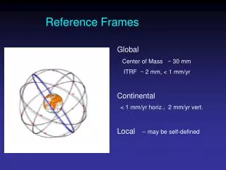
GNSS, Vertical Land Motion, and Reference Frames
GNSS, Vertical Land Motion, and Reference Frames. Peter Clarke Professor of Geophysical Geodesy, Newcastle University, UK. TOPICS FOR THIS AFTERNOON. What is GNSS? How does it measure position? What limits its accuracy ? -------------------------------------

GNSS, Vertical Land Motion, and Reference Frames
E N D
Presentation Transcript
GNSS, Vertical Land Motion, and Reference Frames Peter Clarke Professor of Geophysical Geodesy, Newcastle University, UK
TOPICS FOR THIS AFTERNOON • What is GNSS? • How does it measure position? • What limits its accuracy? ------------------------------------- • How do we define coordinates? • What can GNSS really observe,and how then do we ‘measure’ what we really want? ------------------------------------- … followed by some examples
A TYPICAL (?) TIDE GAUGE SITE: BRST www.epncb.oma.be
WHAT IS GNSS? • NAVSTAR (GPS) • GLONASS • Galileo • Beidou • Constellations of MEO satellites (andsome GEO for Beidou) transmittingstable microwave signals which canbe used for ranging
THE GPS CONSTELLATION AND SIGNAL • 24 (nominally) satellites • 20,200 km altitude • 11h 58m period • transmit microwave radio signal • Two carrier frequencies • L1: 1575.42 MHz (λ = 0.190 m) • L2: 1227.60 MHz (λ = 0.244 m) • just sine waves, contain no “information”
THE GPS SIGNAL AND PSEUDORANGE • Binary phase shift key (BPSK) modulation • by multiplying the carrier wave by a sequence of +1’s and -1’s, we can send digital information • ‘+1’ represents 1, and ‘-1’ represents 0 • digits are transmitted at 1-10 Mbps • Each satellite’s transmitted sequenceis “pseudo-random” • each digit leaves satellite at known time • by correlating with receiver’s copy ofsequence, can determine satellite-receiver “distance” ?
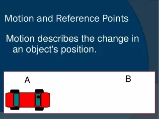
HOW DOES GNSS MEASURE POSITION? • Consider the 2-D case: • two known objects, two measured distances • Trilateration d2 d1
ESTIMATING POSITION AND TIME TOGETHER • Reconsider the 2-D case, but with 3 satellites and common timing errors
GPS POINT POSITIONING 95% errors <20m ?
THE CARRIER PHASE • So far, we have been concerned with pseudoranges derived from the code • observed C/A and P-codes, correlated with receiver copy • But the carrier also contains range information • amplitude A varies sinusoidally with phase(distance along the signal, or time)
WHAT’S IN THE GNSS PHASE SIGNAL? • GPS carrier phase observation model: L receiversatellite where receiverfr0) and (satellite fs0) therefore L frfs00 N) L crs) constant where:c(TrTs) ctrtsclocks) |rr(tr)rs(ts)|cclocks catmos • Where is the geophysical information here? • and how can we use these observations to “see” it?
WHAT LIMITS GNSS ACCURACY? Orbit Error Clock Error (Selective Availability) Ionospheric refraction Tropospheric not to scale refraction Multipath Antenna height Geophysical changes in site position Receiver Noise
FORCES ON SATELLITES • Kepler’slaws of satellite motion derived from • Newton’s Universal Law of Gravitation (NG) • Newton’s Second Law of Motion:F =ma = GMm/ r2era = GM / r2er • Problems: • NG is only true between pairs of point masses, or between spherically symmetric masses • Earth is only approximately spherically symmetric • there are additional gravitational forces (Sun, Moon,...) • there are also non-gravitational forces …
IONOSPHERIC DELAY • Ionosphere delays radio signals • upper atmosphere: 50-1000 km (peak @ 350 km) • Sun’s UV rays cause atom electron positive ion • electrons delay the coded signal, and advance the phase: ion(f) ≈ k / f 2 • k varies unpredictably with time and direction • Observations at L1 and L2 frequencies: ion(L1)≈k / f12 ion(L2) ≈ k / f22 • so f12 ion(L1)– f22 ion(L2)≈ (k - k) = 0 • “ionosphere-free” combination LC is defined: (f12 L1–f22 L2) ≡ (f12 – f22) LC
HIGHER-ORDER IONOSPHERIC EFFECTS Petrie et al. (2010), JGR N 1st-order ionos only IG 2nd- and 3rd-order included IG2 2nd-order included, but not 3rd
TROPOSPHERIC ERRORS(1) the “dry” troposphere • The troposphere is a non-dispersive medium • carrier phase and code signal are both delayed equally on L1, L2 • the stratosphere behaves similarly • Most of the tropospheric delay is attributed to the dry atmosphere (O2 and N2) • depends on amount of air above the receiver • i.e. air pressure and temperature • therefore varies with height above sea level and latitude • At sea level, the zenith delay is ~ 2 m • use a mapping function to relate this to the delay at lower angles
TROPOSPHERIC ERRORS(2) the “wet” troposphere • A smaller part of the delay is caused by water vapour (not liquid water) • maybe around 0.2 m at zenith • Highly variable • climate, altitude, etc. • most water vapour is in bottom 1.5 km of troposphere • very little above 4 km (normal top of clouds) • Highly significant for phase GNSS • must estimate residual zenith delay (and lateral gradients) as time-varying parameter, using “wet” mapping function
MULTIPATH • The GNSS signal may arrive at the receiver directly, or reflected off a nearby object • these will interfere with each other • also get imaging effect similar to “ghosting” in TV • Multipath can cause loss of lock • especially in a moving receiver, orin urban environments • Can have multipath fromseveral reflectors at once
EFFECTS OF MULTIPATH • Measured pseudorange may be increased or decreased by up to half a chip length • in practice, rarely > 1/4 chip length • Multipath bias will be periodic • periods of several minutes • short-term averaging will not help • Imaging bias is constant • even long-term averaging is useless • Multipath can be mitigated in a several ways • antenna design, filtering, modelling, ... Lau & Cross, J. Geod., 2007
SATELLITE ORBIT GEOMETRY AND MULTIPATH • Earth rotates once per sidereal day • a solar day (24h) is slightly longer because Earth orbits the Sun • the sidereal day is (365.25/366.25) x 24h ≈ 23h 56m • GPS satellites orbit Earth in 11h 58m • in one sidereal day, they orbit exactly twice • from ground, apparent satellite positions recur • geometry (DOP) + multipath errors repeat exactly • GLONASS satellites orbit Earth in 11h 15m • i.e. 2⅛ times per sidereal day • because there are 8 satellites per orbital plane, approx geometry (as seen from the ground) and DOP will repeat every sidereal day
ANTENNA PHASE CENTRE VARIATIONS Examples of the antenna phase patterns determined in an anechoic chamberThe actual pattern in the field is affected by the antenna mount To improve observation modelling, and especially to avoid height errors, we must account for PCV variations by using at least a nominal model for each antenna type Figures courtesy of UNAVCO
SUMMARY SO FAR • GNSS satellites transmit radio signals whose timing (phase) is tightly controlled by a central atomic clock • satellites’ positions can (mostly) be physically modelled • We can use the received phase to measure ranges between multiple satellites and ground receivers • must account for atmospheric variations in c and antenna calibration, and minimise multipath error • This gives us the instantaneous positions of the receiving antennas
THE STORY CONTINUES … • How do we define coordinates? • what do they mean? • What can GNSS really observe,and how then do we ‘measure’ what we really want? • using terrestrial reference frames
HOW DO WE DEFINE COORDINATES? Z • Origin at centre of Earth • Right-handed set of axes • Z-axis through North Pole • X-axis through Greenwich meridian • Actually, it’s notthis simple! North Pole G P Y X
SOLID EARTH TIDES • aka “Earth body tide” • Direct gravitational attraction of Sun and Moon deform Earth • greatest at Equator (~±0.25 m) • smallest at Poles (~±0.05 m) • effects of Sun ~1/2 of Moon • Harmonic periods 8 h – 18.6 yr • predominantly semi-diurnal (~12 h)and diurnal (~24 h) signals • Must be accounted for • models accurate to ~1%
OCEAN TIDE LOADING DISPLACEMENTS • Same periods as Earth body tide • Everywhere on Earth affected at >=1mm level • UK one of largest signals on Earth • ±100mm in absolute terms
EFFECTS OF TIDAL MISMODELLING • Until recently, assumption was sub-daily signals average to zero in 24h solutions used in geodesy • King et al [2003] and Penna and Stewart [2003] showed that unmodelled sub-daily systematic errors propagate into longer period signals • Ambiguity fixing changes the effect, but does not always reduce it King et al. (2003), J. Geodesy Penna et al. (2008), JGR
COORDINATE REFERENCE SYSTEMS • A reference system is the complete specification of how a coordinate system is to be formed • defines • origin of the coordinate system (e.g. centre of mass of Earth system) • fundamental axes of the coordinate system (Greenwich etc.) • scale (e.g. based on speed of light) • celestial (inertial) ref. sys. needed for satellite orbit modelling • terrestrial (Earth-fixed) ref. sys. needed to describe ground coords • A reference frame consists of a set of identifiable fiducial points along with their coordinates • e.g., ground marks and their coordinates • serves as the practical realisation of a conceptual reference system • associated constants, models, and algorithms (“conventions”) used to transform between observations and reference data
TERRESTRIAL REFERENCE SYSTEMS • Certain ground station coords/velocities held fixed, stars seen to move • International Terrestrial Reference System (ITRS), used in geodesy • geocentric, the centre of mass being defined for the whole earth, including oceans and atmosphere. • the unit of length is the metre (SI). • orientation(axes) initially given by the BIH (now International Earth Rotation & Reference Frames Service) orientation at 1984.0 • time evolution of the orientationensured using a no-net-rotation (NNR) conditionwrt horizontal tectonic motions over the whole earth
TRANSFORMING BETWEEN ICRS & ITRS • To transform from the terrestrial reference system (TRS) to the celestial/inertial reference system (CRS) at the epoch (t) : where Q(t), R(t) and W(t) are 3x3 rotation matrices: • Q(t) arises from the motion of the celestial pole (CIP) in the CRS: precession and nutation • R(t) arises from the spin of the Earth around the CIP • W(t) arises from changes in the solid Earth’s rotation axis wrt the CIP: polar motion
satellite orbital ellipse perigee f(t) a1e geocentre ellipse centre i ae equator ascending node vernal equinox WHAT CAN GNSS REALLY MEASURE? • Satellite/receiver network geometry (distances/angles) • scale subject to errors in orbit and atmos delay modelling • Orientation of network relative to CIP spin axis • but long-term motion of CIP wrt CRS limited by orbit model • Distances from geocentre (CM) • subject to orbit/atmos errors • But not • long-term orientation • conventional XYZEarth-fixed axes
HOW DO WE “MEASURE” WHAT WE WANT? • Process 24-h batches, removing body tide / OTL • Apply minimum/loose constraints to align to TRF • TRF incorporates other data / conventions to eliminatedatum deficiency • e.g. ITRF2008 • scale+rate from VLBI & SLR • orientation from VLBI, rate (indirectly) from NNR condition • origin+rate from SLR • alignment is sensitive to choice and number of sites used, and their unmodelled motions Bevis et al. (2012), J. Geodesy
THE INTERNATIONAL GNSS SERVICE • Produces precise satellite orbits, clocks and site coordinates consistent with ITRF, which can be used to compute ITRF positions of other sites www.igs.org
A TYPICAL (?) TIDE GAUGE SITE: BRST www.epncb.oma.be
A TYPICAL (?) TIDE GAUGE SITE: BRST www.epncb.oma.be
ESTIMATING VERTICAL LAND MOTION • Must account for: • unmodelledseasonal displacements (loading, errors, etc) • affect rate estimate if span < 2.5yr (Blewitt & Lavallée, JGR, 2003) • coloured noise (time-correlated errors) in coordinates • affect confidence limits and rates (Williams, J. Geodesy, 2003; Williams et al, JGR, 2004) • white-noise confidence estimates typically too low by ×5-10 • equipment (and firmware?) induced offsets • effect is equivalent to random walk noise (Williams, JGR, 2003) • differential movement of GNSS and TG
SUMMARY • GNSS satellites transmit phase-stable radio signals • Received phase (range) gives us the instantaneous positions of receiving antennas • Conventional models, and a reference frame, are needed to develop coordinate time series • Estimated rates of motion must account for seasonal signals, offsets, and coloured noise Peter.Clarke@newcastle.ac.uk