AS-74.3199 Wireless Automation
150 likes | 298 Vues
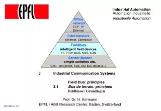
AS-74.3199 Wireless Automation. Implementing PIDPLUS for Halvari system. Halvari – a ball balancing system. The goal is to keep the ball and the cart in the middle. Can be controlled by a manual joystick or a computer.

AS-74.3199 Wireless Automation
E N D
Presentation Transcript
AS-74.3199 Wireless Automation Implementing PIDPLUS for Halvari system
Halvari – a ball balancing system • The goal is to keep the ball and the cart in the middle. • Can be controlled by a manual joystick or a computer. • The position of the ball (angle φ) and of the cart (coordinate y) are measured and their derivatives calculated. Thus our system has four states from which a control variable (force F) can be derived. • In optimal control force is calculated as a linear combination of the states
Halvari – a ball balancing system Halvari can be described with two nonlinear differential equations The constants used in the equations Mass of the cart without the ball Mass of the ball Ball’s moment of inertia Radius of the arch Radius of rotation Acceleration of gravity
Halvari – a ball balancing system The linearized form is derived by assuming that the angle φ is small. Thus we have the following assumptions: The linearized equations are
TraditionalPID • PID controller consists of three terms: proportional, integral and derivative. • The input of a PID controller is an error signal which is the difference between a reference signal and the measured output of the process: P yr u y + e Σ I Σ process - D
PIDPlus • Inwirelessautomation loss of measurement and control data is common • Traditional PID doesn’t handle packet loss that well and gives a poor dynamic response • The solution is to replace PID’s integral part with a filter that takes packet loss into account PIDPlus • PIDPlus holds on to the last filter output until a new measurement is received and after that it calculates a new filter output from the last controller output and time elapsed since the last communication
PIDPlus integral Source: Addressing Control Applications Using Wireless Devices, Emerson Global Users Exchange The filter eguation:
PIDPlus derivative The derivative term is described by the equation Because the reference signal is 0 there is a connection A filter has to be added to the derivative term. The filter equation is (angle φor place y)
Halvari: Joystick Control DAC1 N1 Joystick N2 N3 N4 ON/OFF CH 18. CH 12. DIR SYSTEM SPEED • Joystick measurement and Joystick ON/OFF • N2 receives packet and uses external pins to relay information to N3 • Range: [0,4095] Physical values: [0,2.5 V] • Measurements range: [1300, 1900] [0.79,1.15 V] • N3 calculates control speed and directionand sends packet to N4 • N4 assigns external pins for speed and direction • Signals are amplified from 0-2.5 V to 0-5.0 V.
Halvari: PIDplus controller ACK CH 18. N3.5 N3 N4 CH 18. CH 16. CART POS. DIR SYSTEM BALL POS. SPEED • N3 receives cart and ball position measurements from the system • If control switch is activated, PIDplus control used • Measurements are sent to N3.5 • N3.5 uses PIDplus algorithm to determine control • Sends control command to N4 and waits for ACK packet • If measurements from N3 not received, old control values used • N4 assigns external pins for speed and direction • Signals are amplified from 0-2.5 V to 0-5.0 V.
Some simulations PIDPlus without any packet loss. red = angle φ blue = place y green = y’ turquoise = φ’
Some simulations PIDPlus with some packet loss. Sampling packet loss probability = 20% and Actuator packet loss probability = 20% red = angle φ blue = place y green = y’ turquoise = φ’ The longest time between updates is about 3 times the sampling time.
Some simulations PIDPlus with a lot of packet loss. Sampling packet loss probability = 40% and Actuator packet loss probability = 40% red = angle φ blue = place y green = y’ turquoise = φ’ Time between updates can be even 9 times the sampling time.
References • Addressing Control Applications Using Wireless Devices, Emerson Global Users Exchange, PowerPoint-show