Download
1 / 31
310 likes | 492 Vues
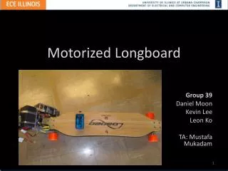
Motorized Longboard. Group 39 Daniel Moon Kevin Lee Leon Ko TA: Mustafa Mukadam. Agenda. Introduction Review Original Design Requirements and Verifications Project Build and Functional Tests Successes, Challenges, and Failed Verifications Other Tests Recommendations for Future Work

E N D
Motorized Longboard Group 39 Daniel Moon Kevin Lee Leon Ko TA: Mustafa Mukadam
Agenda • Introduction • Review Original Design • Requirements and Verifications • Project Build and Functional Tests • Successes, Challenges, and Failed Verifications • Other Tests • Recommendations for Future Work • Acknowledgements, Questions, and Comments
Introduction • Alternative, environmentally-friendly mode of transportation over short distances. • Project aims to provide a commercially viable motorized longboard. • Longboard both friendly to novice users and improves user experience for advanced riders Source: www.loadedboards.com Source: www.elasticpanda.wordpress.com
Features • Hand-held remote controller • Kill switch as safety net • Assisted turning • Speeds up to 15mph
Specific Level Block Diagram 9V Battery 9V Battery Motor Controller Single Motor
Original Design • Incorporate regenerative braking • Low returns • Dual wheel assisted turning • Cost and inefficiency • Implementation of acceleration • Improved conceptuality
Hardware Overview • Microcontroller • Arduino Uno • Motor • Great Planes RimfireOutrunner Motor 1.60 • Motor Controller • Hobbywing 70A Platinum HV Motor ESC • Receiver and Transmitter • Xbee Module 802.15.4 1MW with Wire Antenna
Hardware Overview • Potentiometer • 2-Axis Joystick • Battery • 38.4 V LiFePo4 Battery • Flex Sensor • Flex Sensor 4.5” by Sparkfun • Infrared Sensor • Sharp Infrared Proximity Sensor Short Range
38.4 V Battery Pack • Outputs 38.4 V +/- 20% • Multimeter consistently measured 39-42 V • Operating range of 4-8 miles • Test run of 4 miles (distance determined using Google Maps) achieved without battery failing
Kill Switch • Ensure flex sensor can read flex of the longboard • Multimeter showed increase of resistance once rider stepped on board • Ensure board does not activate motor with no rider • PWM output shown on oscilloscope to be 1 ms (0 mph) with no rider
Motor • Ensure communication between motor and motor controller • Motor was run with hardcoded PWM and rotation was achieved • Must provide enough torque to propel rider and longboard at least 13 miles per hour • Rider was able to cover 100 yards in less than 15 seconds, signifying speed above 13 mph
Turn Assistance • Making a turn results in IR output • IR sensor was tested independently with Arduino and multimeter, and a range of 0.65 V – 1.1 V seen • Change in IR output results in change of PWM • IR sensor tested with Arduino and PWM monitored, and PWM change seen when turning (minimum of 0.985 x PWM for left turns, maximum of 1.01 x PWM for right turns)
Turn Assistance • When left turn is detected, PWM will decrease by a factor based on the sharpness of the turn. (min 1%) • When right turn is detected, PWM will increase by a factor based on the sharpness of the turn. (max 1%)
Remote Controller • User is able to hold the controller in one hand • Controller components • Potentiometer, Battery, Button, On/Off switch and XBee • Joystick potentiometer – analog signal • Potentiometer outputs 0 - 3.3V to XBee • Brake button – digital signal • Button outputs 3.3 V to XBee when pressed • Registered Signal • Arduino Terminal printed correct signals
Remote Battery • Outputs 12 V +/- 5% • Multimeter consistently measured ~12.3 V • Provides adequate power to remote components • 5 V and 3.3 V regulator used to power XBee adapter and potentiometer respectively • Battery lifetime • Battery provided a lifetime of 15 hours
Transceiver • Xbee Module 802.15.4 1MW with Wire Antenna • Wireless communication • Communicates properly to distance of 75 ft • Power Supply • 5V regulator to XBee adapter – 3.3 V to XBee • Instantaneous communication • Data is sent at 30 Hz
Micro Controller • Arduino Uno • Power Supply • 9V are supplied to the Arduino • Shield supplies 3.3 V to XBee • Processes the signals from sensors and XBee • Analog - kill switch, IR sensor • Digital - braking • PWM - acceleration • Outputs the correct signal to the motor controller • Thresholds were calibrated to minimize mistakes • Code printed correct outputs to Arduino terminal
Successes • Board does not move when there is no rider • Delay of ~1 second • Increases/decreases PWM when joystick is tilted • Constant speed when joystick is in neutral position • Board decelerates when brake button is held • Decreases PWM at a greater rate than joystick • IR sensor detects turns • increases/decreases PWM by calculated ratio when turn is recognized
Challenges • Compatibility between modules • PWM output of XBee requires low-pass filter before going to analog input of Arduino • Conversion of analog input to throttle signal compatible with motor controller • Slip prevention • Added duct tape to wheel driven by motor • PWM Calibration • Level of acceleration/deceleration • Speed Difference with/without Load • Changes according to tilt of board Low-Pass Filter
Challenges • Assisted turning implementation • Flat change versus ratio • Limited turning radius • IR sensor on different surfaces • Brake time on different surfaces • Influence of topography
Failed Verifications • Regenerative Braking • Low returns ~5% • Reverse function • Brushless DC Motor • High Power 3-Phase H-bridge • Power MOSFETS, proper heatsinks
Other Tests • PWM Calibration • Must make sure longboard accelerates at speed desired by primary rider • Active Drive Calibration • PWM increase or decrease must be proportional to turn seen, and only in the ranges desired ranges • Flex Sensor Calibration • Kill switch must not activate if a small “no-rider” state is detected
Future Recommendations • Reverse Function • Smoother acceleration • Switches and Low battery detection • Lighter and more compact implementation of board • Efficient regenerative braking • Dual wheel drive • Ergonomic Controller
Acknowledgements • A big thank you to: • Board Members of the Student Leung Venture Fund • Kyle Chin and Loaded Longboard • Scott and Dave from the ECE Machine Shop • Dan from the ECE Parts Shop • Professor Carney and our TA Mustafa Mukadam • Everyone who is in attendance at our presentation