Download
1 / 16
160 likes | 273 Vues
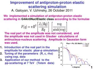
Discussing cross-angle corrections in elastic scattering analysis, including systematic errors and coordinate space asymmetries. Results compared pre and post corrections and cuts. Estimation of corrections for different scenarios explained.

E N D
Elastic pp scattering, AN and r5 • Mostly stuff shown in the previous pp2pp/STAR meetings • A little bit about the cross-angle corrections (in angle vs in coordinates) Kin Yip Collider-Accelerator Department Brookhaven National Lab. Nov. 15, 2011, STAR Collaboration Meeting
Before cross-angle corrections Obviously, no fiducial cuts and hotspot cuts applied in both cases. After cross-angle corrections for the East ( -100 rad, 60 rad) All these plots are for all runs. Kin Yip
Before Before After After Kin Yip
After cross-angle corrections • With fiducial and hotspot cuts Kin Yip
Kin Yip • I’ve used Steve’s Sep. 29 transport, Igor’s latest correction and the crossing angle corrections (including hotspot/fiducial cuts). • Systematic errors: (0.03 rad.) and instead of t/t ~10% for all –t bins, I’ve read off the t/t values from JH’s Sept. 21’s talk : • Systematic errors include those of beam divergence & offset, geometry and Leff. • Re(r5) = 0.00124 0.00255 Im(r5) = 0.00751 0.04124 • Compared with when t/t ~10% (and no error in ) : Re(r5) = 0.00124 0.00312 Im(r5) = 0.00719 0.04834
Kin Yip • After all corrections/cuts previously mentioned
2009 3 2 1 2003 Kin Yip
After cross-angle corrections ( -100 rad, 60 rad) -100 rad & 60 rad are in fact from the asymmetries in coordinate space: -2.5 mm (x) and 1.5 mm (y). Divided by Leff if (Leff = 25), you get those -100 rad & 60 rad . After cross-angle corrections ( -2.5mm, 1.5 mm) All these plots are for all runs. Obviously, no fiducial cuts and hotspot cuts applied in both cases. Looks identical. Kin Yip
Before After cross-angle corrections ( -2.5mm, 1.5 mm) All these plots are for all runs. Obviously, no fiducial cuts and hotspot cuts applied in both cases. Kin Yip
After cross-angle corrections in coordinates ( -2.5 mm, 1.5 mm ) Differed by ~0.005 mradians or 5 radians. Kin Yip
After cross-angle corrections in coordinates ( -2.5 mm, 1.5 mm ) Kin Yip
After cross-angle corrections in coordinates ( -2.5 mm, 1.5 mm ) • Though most Leff is ~25, but for the vertical pot in y, Leff is more like 22.9. • 1.5mm / 22.9 ~ 65.5, rather than ~60 -radians. • I can similarly estimate the effect if we include x0/y0 corrections … • I didn’t do the fiducial/hotspot cuts in this case of using coordinates (as cross-angle corrections or whatever you call) as people are still discussing various options/methods and it takes quite a bit of time to do. Kin Yip