Download
1 / 17
170 likes | 351 Vues
LBT AO Real Time Software. Roberto Biasi, Mario Andrighettoni, Dietrich Pescoller Microgate S.r.l. Via Stradivari,4 39100 – Bolzano Italy. Outline. Hardware platform Software platform and Programming language Interfaces (communication) Slope computer SW Real Time Reconstructor SW

E N D
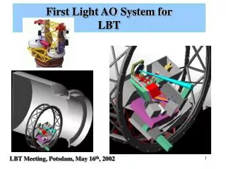
LBT AO Real Time Software Roberto Biasi, Mario Andrighettoni, Dietrich Pescoller Microgate S.r.l. Via Stradivari,4 39100 – Bolzano Italy
Outline • Hardware platform • Software platform and Programming language • Interfaces (communication) • Slope computer SW • Real Time Reconstructor SW • Mirror Control SW • Safety issues • Performances
Hardware platform • Real time software: Analog Devices TigerShark DSP • 32 bit floating point • Super-Harward architecture • SIMD: Single Instruction Multiple Data • Internal clock 242.86 MHz 485 32 bit floating point Mmac/s (if properly programmed…) • Diagnostic: NIOS embedded processor, implemented on Altera Stratix FPGA • 32 bit RISC processor, clock 60.7 MHz • Offloading of several tasks on FPGA • ‘Internal’ and ‘external’ connectivity among the main design goals from the beginning, no bottlenecks !
Software platform/programming language • Real time software: TigerShark assembly only ! Why ? • Performance loss using C is all but negligible (~2.5x) • AD assembly language is ‘relatively’ readable • Diagnostic software (NIOS): C/C++ • Operating System • All real-time software is OS-free! • It’s a hard real time environment with very few tasks and very limited interaction between tasks • We never felt the need of an operating system
Interfaces –communication • Data transfer latency is a critical aspect in parallel computers • Strict separation between real-time communication and diagnostic communication • Real-time • Used to transfer real-time data (slopes from Slope Computer to Real Time Reconstructor, intermediate data of parallel processing), in a time deterministic way • Based on 2.125 Gbit/s Fibre-channel physical standard (layer 0, 1) • Thoroughly handled by HW (FPGA) • Up to 4.25 Gbit/s ‘raw’ communication speed (two channels paired), 3.3Gbit/s typical data throughput • Robust protocol (CRC control)
Interfaces –communication (cntd.) • Diagnostic • Used to transfer diagnostic data (circular buffers), system configuration (code and coefficients uploading), operation (change operating mode), housekeeping (temperatures, currents, …) and maintenance (firmware upgrades, …) • Access to all devices embedded on BCU and DSP boards (DSP, SDRAM, SRAM, FPGA, SRAM). Memory mapped access. • Based on Gigabit Ethernet, dedicated UDP/IP protocol (MGP). Now we are convinced it has been a good choice • UDP stack implemented on NIOS soft-core embedded processor (BCU FPGA) • Speed: currently ~90MBit/s actual data throughput. Main bottleneck on host PC. Improvement margin also on BCU.
Write_sequential: the source data vector is split among the destination devices, writing different data to the same internal addresses • Read_sequential: data are read sequentially from the same internal address of the devices Interfaces – communication primitives • Small set of low-level primitives • Write_same: copies a data vector from source memory to the same internal addresses of all destination devices (e.g. DSPs)
Interfaces – diagnostic buffers • Same concept very extensively used on MMT336 • On each DSP board, 6 linear or circular buffers can be filled with the content of any DSP memory location (single location or contiguous vector). • Bi-directional (content of buffer is written to a DSP memory location) • Sampling occurs at each local control cycle (~71 KHz) • Decimation • Triggering on logic condition (=, , <, >) occurring on another memory location • Buffering management and data storing handled by FPGA. No DSP SW overhead, DMA memory access • 64 Mbytes available on each DSP board, dynamic memory allocation
Slope computer • Implemented on a single BCU (1 TigerShark DSP) • Direct interfacing to SciMeasure LittleJoe through AIA interface • The slope computer is also the arbiter of the RTR operation. Sequencing of operations relies on determinism of real-time communication • Time master is the frame sync signal from CCD controller
Slope computer • Through the LUT, the user specifies how many new slopes can be computed by the DSP • Pipelined operation • CCD is sampled by SciMeasure LittleJoe • Data transfer through standard AIA port, connected to BCU PIO port • The BCU FPGA sequences the pixel data into DSP memory, according to a user-definable LUT • The BCU DSP performs slopes computation, sequences the AdSec RTR operation and stores the diagnostic data
On-sky interaction matrix calibration User-definable parameters. soff,0 can be modified on-fly Slope computer Pixel offset & gain correction: Start_of_frame Slopes calculation: Pixel reading ‘regular’ Slopes computation OR where: Average flux normalization RTR management OR User-defined constant norm. Slope correction:
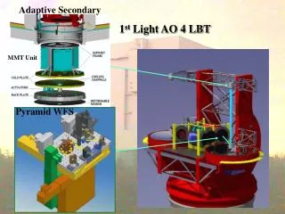
Real Time Reconstructor • Implemented on the Adaptive Secondary control electronics • Parallel computing: every DSP computes 4 outputs • Parallel operation sequencing and data distribution managed by Slope Computer • Very efficient data re-circulation through real-time communication
Actual mean gap Control forces pseudo-integrator (offloading to feedforward) Max N=3, M=4 Real Time Reconstructor Checked by Slope Computer Start_RTR end_of_RTR=TRUE end_of_MM=TRUE Start_MM Triggered by Slope Computer Start_FF update_FF = TRUE To control routine Can be swapped on-fly: • [G] diag.matrix (global gain) • [B] gain matrixes • BF0 BF1 AF1 force integrator coeffs.
Local mirror control Capsens ADC EOC Interrupt start (capsens ready) • Loop runs @ ~70kHz (capsens sampling @ ~140kHz) • Computational time: 2.4µs (Total time for 4 channels handled by each DSP.) • 16% of CPU time used by local control algorithm Capsens linearization Position compensator (4/4 IIR on pos.error) Velocity compensator (4/4 IIR on position) Write to drives DACs
Timing SOF Pixel readout Slopes computation RTR and FeedForward 1 2 3 4 5 6 7 1 2 3 4 5 6 7 1 2 3 4 5 6 7 SC: EEV39 (80x80), no binning RTR: 3/4 IIR filter, modal control, 672 modes (order of filter does not affect computational time !) P45 LBT672 Pixel readout (SciMeasure LittleJoe) 850µs 850µs Slopes computation ~ 0 µs (pipelined) ~ 0 µs (pipelined) 1: transfer of 1256 slopes to DM2 crates 25µs 13µs 2: last tap of RTR IIR filter 7µs 7µs 3: modes vector re-circulation 8µs 20µs 4: commands calculation (modes to pos) 3µs 35µs 5: commands vector re-circulation 8µs 20µs 6: feed forward currents calculation 3µs 35µs 54µs 130µs 7: FFWD currents check (Slope Comp.) 5µs 35µs
Safety (shell…) • The Slope Computer can perform efficiently global checks on position commands, feedforward force commands, modal amplitudes • Check of position and modal amplitudes has moderate cost in terms of time (~5µs each): data are re-circulated anyway ! • Check of feedforward currents more time consuming (read, check and write): ~35µs • Policy in case of exceeding command (To Be Tested): • Skip thoroughly external loop control cycle (= keep old mirror commands) • Apply only ‘acceptable’ commands, replace exceeding ones with old commands
Conclusions • The real time SW, including diagnostic and real-time communication, performs as expected by initial design. We are happy… • Development completed ! Minor issues: • Minor refinement and interface debugging with high level interface • ‘shell safety’ policy still to be decided