Download
1 / 45
450 likes | 583 Vues
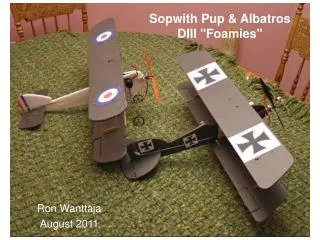
Sopwith Pup & Albatros DIII "Foamies". Ron Wanttaja August 2011. Features. Two airplanes, nearly identical in construction Weight, with all electronics 175 grams ready to fly with 500 ma battery – 6.2 oz 145 grams (not including battery) Wing area: 1450 sq-cm (148 sq inches)

E N D
Sopwith Pup & Albatros DIII "Foamies" Ron Wanttaja August 2011
Features • Two airplanes, nearly identical in construction • Weight, with all electronics • 175 grams ready to fly with 500 ma battery – 6.2 oz • 145 grams (not including battery) • Wing area: 1450 sq-cm (148 sq inches) • Recommended motor/prop • Park 250 – 8 x 6 slow flyer prop • This is almost too much motor –produces ~230 oz of thrust with a fresh battery (greater than 1:1 thrust to weight ratio) • Can fly with small ~180-class motor…but the extra thrust is nice, when you need it. • Construction material – Everything! • Fuselage 6 mm Depron foam • Wings 6 mm Depron foam (3 mm is OK) • Fuselage stiffener/motor mount – ¼" x 5/8" bass or balsa stick • Wing struts: 1/16" plywood • Assembly: foam-safe CA, #4 nylon bolts/nuts
Design Philosophy • The design is a true "composite" using a variety of materials • Depron foam (3 mm & 6 mm) for large surfaces like wings and fuselages • Plywood for stiffening • Bass or Balsa "motor stick" to provide a basic structure • Biplane design gives good wing stiffness using even 3 mm Depron • Thin leading-edge reinforcement helps, too • Commercial kits/ready-to-fly designs put you at the mercy of the manufacturer for spare parts • These planes let you make all your parts • The airplanes are designed to be easily repaired • Wings are actually bolted to the fuselage using #4 sized nylon nuts/bolts • The ~5 nut/bolt sets used on the design weigh a total of only 2 grams • Break a fuselage? Glue it back together, or cut out a new one, bolt the motor stick and wings to it • Break a wing? Glue it back together, or unbolt the assembly, cut off the foam from the plywood struts, and glue on another wing • Break a motor stick? Glue it back together! • Never have broken any other wood part on a biplane! • Design supports experimentation, too • Can make other types of aircraft with just minor changes to wing or fuselage shape
The Real Machines • The Sopwith Pup was a predecessor to the famous Sopwith Camel • Its actual name was the Sopwith "Scout," but was called the Pup due to its similarity to larger Sopwith 2-seater • It entered combat in late 1916 • The Albatros DIII entered combat in early 1917 • It had a plywood semi-monocoque fuselage, similar to a modern aircraft only in wood • Most of the WWI German pilots used Albatros • von Richthofen had more "kills" flying an Albatros than his Fokker Triplane
A Construction Note or Two • The "glue" is "Foam Safe" Superglue (Cyanoacrylic, or CA) • Non-foam-safe kind can be used to bond the wood parts • Get the small spray bottles of "catalyst" or "Kicker" to get the CA to cure fast • Cut the Depron foam with an Exacto knife • The 3mm foam can be easily cut with a good set of scissors • Buff the rough edges with ~80 grit sandpaper • Don't worry about cutting smooth curves…cut it out, then smooth it with the sandpaper • When cutting foam, consider making spare parts • It's a lot easier when you're set up for it • The wings are quick and easy to cut out…make some spares • These instructions assume using an interconnected rudder and aileron system • Can go to full four channel (throttle, aileron, elevator, rudder) • Can go rudder-only if desired, but need to build in a bit more dihedral angle (see notes on strut pages
Front Half of Pup Fuselage Pattern Print out the two halves of the fuselage, tape together at the line This notch sets the angle of incidence for the wing system Best Fuselage thickness seems to be 6 mm. 3 mm works, but is a bit more brittle
Rear Half of Pup Fuselage Pattern Approximate Horizontal Stabilizer Slot Rudder Line Include the entire shape of the tail (rudder included) when cutting out the fuselage. Then cut off the end for the rudder as shown. If using 6 mm foam, use the cut-off rudder as a pattern for a 3 mm rudder.
Front Half of Albatros Fuselage Print out the two halves of the fuselage, tape together at the line
Pup Wings • Basic wing shape is a rectangle – 4.25" high, 26 inches wide • Use pattern to shape the wingtip • Need two wings! • 6 mm depron, can go 3 mm for less weight but more fragile • Surprisingly little weight advantage Leading Edge Wing Construction – Make Two Wingtip Shape Wings are 26" span Cut Rectangle 26" long and 4.25" Wide from 3mm or 6 mm foam Lay template at each end and cut wingtip shape
Albatros Wings • Basically identical to the Pup, just with a different wingtip shape and the short length of the wing forward • I actually made the first Albatros' wings from a set of spare Pup wings • Just re-shaped the tip Leading Edge Wing Construction – Make Two Cut Rectangle 26" long and 4.25" Wide from 3mm or 6 mm foam Albatros Wingtip Shape Wings are 26" span Lay template at each end and cut wingtip shape
Pup Horizontal Stabilizer/Elevator • 3 mm depron • Notch at leading edge is the width of the fuselage foam 1” Construction Cut out from 3mm foam (scissors works fine) Cut 1" wide strip at end (elevator) Join with hinge material (Packing tape or 1/8" strips of hinge fabric) Cut out elevator "notch" to let rudder swing Bond in wire "Bridge" using foam-safe CA on sides ONLY No Glue Here! ~.032" piano wire Glue here
Albatros Tail • Elevator shown in actually a bit too big! • A bit sensitive in flight • Cut a bit off the trailing edge of the elevator if your controller won’t reduce travel
More on Hinges Strips of ½A control hinge fabric - Internal Strips of clear plastic packing tape • Cut to 1/8" wide • Use exacto to cut slot • CA in place Hybrid Strips of ½A control hinge fabric - External • Glue hinge material to control surface only • Use packing tape to attach surfaces • Easily removed/repaired • Cut to 1/8" wide • Lay on surface • CA in place
Wing System Center Struts and Wing Struts are the same height and slant – easy to keep straight during assembly Leading Edge/Landing Gear Brace installs in slot in Center Strut
Glue to plywood with rubber cement, or print on label stock Odd bumps and bulges at the ends of the struts are just for drawing convenience. Holes for Gear Bolts Pup Wing Struts Top and bottoms are basically identical, so the struts can go either way Center Strut Leading Edge & Landing Gear Brace Formerly had a triangular brace in the middle of the lower wing - Deleted All are one-piece 1/16" plywood Cut slot to the thickness of the wood used
Alternate Pup Wing Struts (Easier to cut out) Glue to plywood with rubber cement, or print on label stock Deeper brace for more dihedral (rudder-only systems) Structurally, these are identical, but they are different appearance if flipped. Leading Edge & Landing Gear Brace "Firewall" Same 1/16" plywood, cut to match motor mount. Can be trimmed after assembly All are one-piece 1/16" plywood
Leading Edge & Landing Gear Brace Albatros Wing Struts Albatros has less wing spacing than Pup…these struts are shorter Mid Brace Formerly had a triangular brace in the middle of the lower wing - Deleted
Simple Albatros Wing Struts Deeper brace for more dihedral (rudder-only systems-either plane) Leading Edge & Landing Gear Brace Mid Brace
Strut Assembly Center Strut Off-Center, since it bolts to the SIDE of the fuselage! Hold gear in place with #4 nylon bolt with plywood washer Leading Edge & Landing Gear Brace Do not glue Mid Brace until final assembly of wing Leading Edge & Landing Gear Brace Landing Gear (0.049" piano wire) Albatros Why, yes, it IS asymmetrical! Pup #4 nylon bolts attach center strut and motor stick to opposite sides of foam fuselage Asymmetrical nature accommodates for the offset of the foam fuselage from the strut Leading Edge of upper wing is even with the upper part of the center strut Bottom Posts go through slits made in Wing. Trim off excess with side cutters. Leading Edge of lower wing butts up against (and is glued to) the forward brace
Wing Assembly Position Center Strut assembly just to the right of the centerline, with the landing gear brace flush against the leading edge of the wing. Press to leave dents from the bottom posts. Leave off the mid brace from the center strut until the slits are finished Score shallow cut in top of lower wing, down the centerline. This is to let the wing bend in Step 4 1 2 Albatros is identical, except the wing is the other way around Slots MUST be parallel to the centerline! Shove Center Strut through slits (it'll pop through). Forward edge of wing should be flush against back of landing gear brace. Add the Mid Brace to the center strut, press against the wing to mark its location, then cut slits. 4 3 Remove center strut, use exacto knife to cut slits where the bottom posts made dents. 6 mm wing shown. For 3mm wing, the bottom of the wing doesn’t go to the bottom of the brace 4 5 Bend up each side of wing, use CA to bond it parallel to the bottom of the Landing Gear Brace. This sets the dihedral. Bond the top and bottom of the wing leading edge to the back of the brace Bond the mid brace also to the wing, trim off excess with side cutters Apply foam-safe CA to the center strut ONLY (not the landing gear or mid braces). Keep strut vertical to wing until CA sets
More on Attaching the Center Strut • Wing alignment isn’t hyper-critical, but attaching the struts to the wings needs a bit of care. The Center Strut is the key component The slots for center strut MUST be parallel to the centerline! Draw a guideline perpendicular to the wing, press the forward tab into the wing, then carefully set the tab location for the rear tab at the same offset to the guide line If the strut is at an angle, the overall wing alignment to the fuselage will be at an angle, too. In flight, the airplane will tend to roll away from the wing that’s “forward.” If necessary, add a shim to where the wing strut bolts to the fuselage to take out the angle Center Strut installed at an angle Shim added between strut and fuselage to set wing at right angle to fuselage Wing-attach bolts (nylon)
Upper Wing System 1 Lightly score top of upper wing to allow flex for dihedral Set the wing lightly atop the strut in the right position (leading edge of wing even with top part of center strut) Remember to offset wing slightly to left to match lower wing Apply pressure to lightly dent the bottom of the wing to show where the tabs go 2 Use Exacto to cut out tab slots at the dents 3 Check fit (no glue), alter slots as necessary Glue wing struts to lower wing and repeat Don't glue the upper wing in place until the entire airplane is done (easier access) 4 Pup and Albatros built the same way
Lower Wing Leading Edge Reinforcement • The "Box" of the biplane wing structure is pretty strong, but there still can be some flex (especially with 3 mm wings) • Bonding reinforcement to lower-wing leading edges adds more stiffness • Use 1/16 x 1/8" spruce strip (available at hobby stores) or thin carbon-fiber strip • Should go at least 3/4ths of the wingspan • IMPORTANT: Need "bridge strip" across front of main strip and landing gear brace to carry load Without bridge strip, loads are concentrated here Bridge Strip is bonded to both the center section and the wing reinforcement strip Pup and Albatros built the same way
Landing Gear Attachment – Leading Edge Graphite Strip Leading Edge Landing gear mounting bolt with plywood washer "Bridge" to center section Receiver velco'd to bottom of wing
Ailerons • Cut out 1" x 3" notch in trailing edge • Make 3mm aileron to fit notch (leave room to move) • Install with hinges • Bend root end of aileron torque wire as shown (~0.038" piano wire) • Cut plywood strip~ 1/8-1/4" wide, 1.25" long, with small holes top and bottom 1" apart ("Horn") • Slide over wire • Slide two bearings over torque wire • Anything that goes loosely around tube • Bend the outer wire to fit under aileron • Cut thin slot near root of wing for the horn, and insert under wing • Position the wire so that it runs from the root to the front part of the notch • Tape the bearings to the bottom of the wing so the wire can still turn • Tape the aileron to the bend end of the wire plywood aileron horn 1" 4" CA wire to plywood aileron horn Plywood strip with two small holes 1" apart Bearings (section of thin tubing, like wire insulation or nylon tubing) Pup and Albatros built the same way Also can use commercial aileron system
Aileron Close-up Fabric Hinge Material Bent end of torque wire, taped to aileron "Bearing" (piece of plastic tube) wire, taped to lower surface of wing
Wing Struts Attachment About 3½" inboard of wingtip – not critical! Both wing struts parallel with Center Strut ½" behind the leading edge of wingtip – not critical, but both sides should be the same Pup and Albatros built the same way
Upper Wing Attachment Place top wing on Center Strut, hold in place Re-assemble wing, repeat on other wing strut Press top tabs of one wing strut into bottom of upper wing to mark position, then slit with Exacto • This method works very well at making a box wing structure with minimum warp • Key factor: top wing should be resting LOOSELY on top of wing-strut tabs prior to marking • Flick the upper wing up slightly before marking to be sure it isn't caught on a sharp point of the strut Pup and Albatros built the same way
Assembly Sequence Glue Center Strut First Top wing is just resting atop tabs on outer struts Lift one wingtip gently so that the strut tabs no longer touch, then set it gently just atop the strut tabs. Then press lightly atop the wing, and cut out slots for the tabs based on the impressions The basic goal is to find where the struts want to attach without friction causing them to touch in a different spot. The foam is stiff, both wings will want to be at the same angle. Glue the wing to the outer strut. Repeat the lifting/gentle touch on the other wingtip, and cut the slots Do NOT glue the second outer strut yet
Bonding the final strut • Attachment point for second outer strut determines if there’s any twist in the wing Right Looking at Wing assembly from directly in Front Wrong Lengthen slots for strut tabs Twist means you see less of the underside of the wing on one side If the wing is twisted, lengthen the attachment slots for the unglued outer wing strut and slide the attachment to minimize the twist The airplane is tolerant of a surprising amount of twisting, as long as you can adjust the ailerons or rudder to compensate
Motor Stick • Main structural member in fuselage is the "Motor stick" • Supports the motor, and provides the solid mounting for the wings • Made of ~1/4" x 5/8" basswood or balsa running length of fuselage • Hobby stores sell stock pieces of these dimensions… don't have to cut them out • Exact dimensions don't really matter • Basswood is more durable…have broken many balsa sticks, but few bass ones Pup and Albatros built the same way
Top View Making the Motor Stick • Cut stick length equal to nose to tail plus a bit extra • Cut two short pieces ~ 1" long • Use CA to glue them both to ONE SIDE of motor stick Top View • Use Razor saw & miter box, band saw, or very good eyeballs to cut stacked end straight • Use CA to glue "firewall" to front of stick • Note the center of the firewall is even with the CENTER short stick Top View Pup and Albatros built the same way
Motor Stick • Press Motor stick lightly in place, make impression with "side sticks" in fuselage • Cut out foam to clear Motor Stick "side sticks" • Drill hole through motor stick near tail, bolt to fuselage using #2 or #4 nylon bolt and nut Pup and Albatros built the same way
Assembly • Slip fuselage over wing, with center strut on the OPPOSITE side of the wing from the Motor Stick Cut slot in fuselage to clear center support • Drill hole through Motor Stick, through Fuselage, and into wing strut on opposite side – install #4 Nylon bolt/nut Cut slot for horizontal stabilizer parallel to motor stick
Other Details Two-sided arm used for rudder/aileron servo. One side has two pushrods, one to aileron, one to rudder Cut out Fuselage foam and mount rudder/aileron servo on right side of motor stick with foam double-faced tape Battery Stub of toothpick for tail skid, glued into a hole drilled into motor stick Mount elevator servo on left side of motor stick with foam double-faced tape Aileron Pushrod (both sides) Long strip of Velcro for battery to allow CG adjustment Bend landing gear legs slightly forward
Aileron Pushrod Commercial aileron hardware shown…this piece is normally the thin plywood strip
Other Side of Servo Inboard easy-link is connected to rudder Outside (both sides of servo arm) to Aileron
Other Details/2 Velcro for Speed Controller Rudder Pushrod (one side) Aileron Pushrod (both sides) Radio Receiver • Radio receiver installed under bottom wing, near center. Cut holes in lower wing as necessary for running servo wires
Other Details/3 • Glue a thin strip of wood (1/16 ply, leading edge strip, etc. on trailing edge of lower wing, bridging the junction between left and right wings • Due to the scoring to allow the wings to bend to the dihedral angle, this is a stress point…the wood keeps the wing from splitting • Pop holes in the upper wing near the center to allow a long screwdriver to reach the quick-adjusts on the aileron/rudder servo arm Upper Wing Lower Wing Trailing Edge of Wing Thin Strip of wood (like leading edge) bonded to junction at trailing edge
Sopwith Markings • Print this page on a color printer • Cut out roundels, glue to surface using thin line of foam-safe CA just inside the outer edge edge • By putting the bit roundels ONLY on the top wing, you can tell from a distance if the plane is turning towards you or away from you • Color on the rudder is blue-white-red • Make rudder from white foam, color with magic markers
Albatros Markings • If installing on Gray foam, cut out iron crosses right at the square to give white background
Flight • CG should be roughly midway between forward edges of the two wings • Built as shown, CG should be about right with the battery near the motor • Should easily take off at 3/4th power with Park 250 motor • Drag of wheels can cause slight nose-over tendency for takeoff…hold a little back pressure • Full power with a Park 250 gives very short takeoff roll • If turning tendency, leave ailerons set neutral and adjust out with Rudder
Repairs • Can fix most foam damage with heavy clear packing tape and/or CA • Most common damage is the wingtips breaking off outboard of the aileron • Airplane will still fly with one wingtip gone! • However, easy fix with tape or superglue • Most common problem is an aft CG • Version V4 moves the wing attachment ~1/2” further aft to help correct
Variations • Wing and tail shapes are just cosmetic…can reproduce other aircraft very easily (or do your own design) • Big motors can sometimes be more trouble than they’re worth • More torque tendency, harder to compensate for • Wing attach system works for monoplanes as well • Leave off struts that go above fuselage • Works a bit better with 6 mm foam for the wings • If use 3 mm foam, put reinforcement strips on trailing edge as well as leading edge • Easier to build, harder to fly (higher wing loading)