Download
1 / 41
1.06k likes | 2.42k Vues
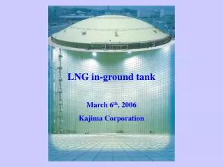
LNG in-ground tank. March 6 th , 2006 Kajima Corporation. LNG in-ground tank: Kajima's construction experience. - From 1976, delivered LNG in-ground tanks of various capacity from 650 kl to 200,000 kl - 26 LNG in-ground tanks in Japan with combined capacity of 2,370,000 kl.

E N D
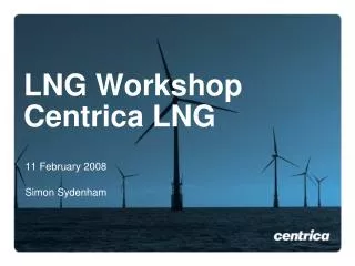
LNG in-ground tank March 6th, 2006 Kajima Corporation
LNG in-ground tank: Kajima's construction experience • - From 1976, delivered LNG in-ground tanks of various capacity from 650 kl to 200,000 kl • - 26 LNG in-ground tanks in Japan with combined capacity of 2,370,000 kl
Structure of LNG in-ground tank Concrete roof Banking • Steel roof / Insulation Side heater Membrane Insulation Concrete segment Side wall Diaphragm wall Gravel layer Bottom heater Bottom slab
Concrete roof Diaphragm wall Membrane
Side heater Bottom heater Concrete segment Insulation
Embedded tank Banking • - Harmonious with the ambient environment • - Highly reliable and safe • - Multipurpose uses of the ground above the banking
Bottom slab structure Bottom slab (pressure-reducing slab) Pressure-reducing slab can be applied to the ground where the water seepage is anticipated to be small.
Earth retaining structure Vertical NATM Earth retaining structure by vertical NATM can be applied to the self-supporting ground where the water seepage is anticipated to be small.
Cryogenic test for concrete structure Determining low temperature characteristics of material • Low temperature bending test • of RC beam Low temperature tensile test of reinforcing bar
Test for frozen soil Determining mechanical properties and expansion pressure of frozen soil Test for frozen soil by using 3-dimensional model Test for frozen soil by using 2-dimensional model
Estimation of strength for RC roof Estimation of strength for RC roof including bucking analysis considering non-linearity of material and shape
Earthquake observation and analysis Determining seismic behaviour based on the analysis from various perspectives, by using a wealth of observation data Wave patterns of the acceleration of the ground and the tank
Air support construction method 2. Assembly of steel roof 3. Air lifting 4. Installation of steel roof • 1. Construction of • side wall 5. Air support construction (concrete placing) 6. Completed
High performance concrete "Supercrete" Cost reduction due to development of Supercrete, a high performance concrete with compressive strength of 80 N/mm2 Verification test of supercrete Supercrete slurry wall
Excavation machine for thinner diaphragm wall Better construction environment and less loosening problems of the natural ground, compared with conventional spraying method Excavation machine for thinner diaphragm wall and finished concrete wall
Self-elevating scaffolding Self-elevating scaffolding can be used for the construction of the structure, such as assembly of concrete segment for side wall, erection of reinforcing bars, installation of outer forms and so forth. Self-elevating scaffolding Assembly of concrete segment using self-elevating scaffolding
Machine for assemblage and erectionof reinforcing bars Assemblage, transportation and installation of reinforcing bars can be done collectively in the working yard. Erection of assembled reinforcing bars
All weather type rapid construction method Roof is assembled, prior to construction of side wall. After that, insulation and membrane are installed concurrently with construction of side wall. → Shortening of construction period (Rapid construction)
In-ground type + Aboveground type (PC, metal) Composite structure of conventional in-ground tank and PC (metal) aboveground tank (Aboveground tank is built on the top of side wall of in-ground tank. )
Steel + Concrete roof type RC roof is built around the outer perimeter of steel roof, to the enlarge inner diameter of the tank →Large-sized tank as much as 100m in diameter
Automated pneumatic caisson method LNG in-ground tank can be built without earth retaining wall and cut-off wall.
Type of LNG tank Single containment tank Elevated base
Double containment tank Reinforced concrete outer tank wall Earth embankment
Pit-in (double containment) tank Reinforced concrete pit Elevated base
Double containment tank Prestressed concrete outer tank wall
Full containment tank Reinforced concrete roof Prestressed concrete outer tank wall
Construction procedure 1. Foundation work 2. Base slab and PC outer tank wall - Soil improvement - Pile foundation PC outer tank wall Base slab Bottom heater
Lift up Assembly of roof PC outer tank wall Bottom of inner tank, Bottom insulation Side of inner tank Liner for the outer shell bottom Liner for the outer shell Bottom PUF panel 3. PC outer tank wall 4. Mechanical work Mechanical work: - Liner for the outer shell bottom - Assembly of inner & outer roof - Lifting up the roof - Liner for the side of outer shell - Bottom insulation - Bottom and side of inner tank
Water pressure test Pressure test Pneumatic test Prestressing PUF panel for side wall 5. PC outer tank wall 6. Mechanical work - Close the opening - Prestressing - Water pressure test - Pressure test - Pneumatic test PUF panel for side wall
Side of inner shell Side insulation PUF panel Side of outer shell liner 7. Mechanical work 8. Mechanical work - Side and roof insulation - Tests & cooling down Start of the operation
Bottom heater Trombone shape type • Conventional type Kajima type
PUF panel PUF cap • Stud bolt PC structure Surface material (in-situ installation) Liner plate PUF (in-situ injection & foam) PUF panel
Construction experience • Petrochemical complex • in Oita, Japan