Cognitive Alarm Clock
Cognitive Alarm Clock. ECE 445: Fall 2005 Alan Carter Carl Salamone. “Wake Me Up Before You Go-Go”. Problem: “I shut my alarm off and go back to bed without ever really waking up” Possible Solutions 1. Place the alarm across the room. 2. Set multiple alarms. 3. Schedule wake-up calls.

Cognitive Alarm Clock
E N D
Presentation Transcript
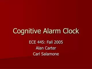
Cognitive Alarm Clock ECE 445: Fall 2005 Alan Carter Carl Salamone
“Wake Me Up Before You Go-Go” Problem: “I shut my alarm off and go back to bed without ever really waking up” • Possible Solutions • 1. Place the alarm across the room. • 2. Set multiple alarms. • 3. Schedule wake-up calls. • 4. Buy a “Cognitive Alarm Clock.”
Cognitive Alarm Clock Is an alarm clock that requires user feedback to disarm the alarm. The purpose is that the user must be fully awake in order to turn off the alarm, preventing the user from oversleeping.
How Does It Work? The Cognitive Alarm Clock presents the user with a random sequence displayed over four led lights. The user must repeat the same random sequence back to the clock to disarm the alarm. The user inputs this sequence through four push-button switches, each corresponding to one of the four led lights.
Design Requirements • Fully functional, 24 hour clock with am/pm notification • User settable 24 hour alarm functionality • Accurate time-keeping • User interface allowing random pattern functionality • Visual & Aural cues to supplement alarm functions
The Brains of the Operation XESS Spartan II FPGA • coded with vhdl • power specifications: • 5 volt power supply • up to ¾ amp draw • output pin capable of 50 mA • parallel cable PC interface • 256kb flash rom capability
VHDL Structure (I) RTCLOCK.vhd - main clock entity. Responsible for organizing and coordinating each of the components into a working clock. • Registers • Other Notable Components
VHDL Structure (II) Registers • htzclk.vhd – clock divider, 1 hz output clock • seconds.vhd – time-keeping seconds register • minutes.vhd – time-keeping minutes register • hours.vhd – time-keeping hour register • ahour.vhd – settable alarm time (hour) • aminute.vhd – settable alarm time (minute) • random.vhd – generates random sequence for alarm
VHDL Structure (III) Other Notable Components • alarmstate.vhd – coordinates the state of the alarm (off, armed, triggered) • simon.vhd – coordinates random sequence with user interface • inputshifter.vhd – records user input and matches with random sequence • display.vhd – coordinates LED time display • ledcontrol.vhd – coordinates LED lights on user interface
VHDL Structure (IV) Sound.vhd Plays four notes, each corresponding to one of the user switch/led combinations. Notes Played: C – 261.64 Hz E – 329.64 Hz G – 392.00 Hz Bflat – 466.16 Hz The sound.vhd file is a clock divider that converts the 100 Mhz system clock into the fundamental frequencies corresponding to each of the four notes listed above.
Software => Hardware • Requirements: • XSA i/o pin connections • Power Supply connection • User Interface • 4-position selectable switch • Hour and Minute increment buttons • Notification LEDs (timeset, alarmset, alarmarm, am/pm) • Random sequence interface (4 LEDs, 4 pushbutton switches)
Power Supply Components • 7:1 Transformer • 6 Diodes • 4700 μF Capacitor • 7815 Linear Rectifier • 7805 Linear Rectifier • 220 μF Capacitor • 4 “C” Battery Pack • 0.75 Amp Fuse
Power Supply Summary • Advantages: • 1. Simple • 2. Inexpensive • Disadvantages: • 1. Very Inefficient (.5 Amp, 10 Watt Loss) • 2. Thermal Losses Require High Speed Fan • 3. PWM Buck Converter : Much Better Option
Testing Procedures Preliminary computer simulations testing all VHDL code modules independently. Continuity testing on all hardware connections. Clock Calibration: Compared displayed time with reliable timepiece. Adjusted clock divider to accuracy within 1 second per hour. (further calibration would be possible with specific testing equipment)
Possible Improvements Problem: Current design too expensive for mass production. Solution: A PIC Microcontroller is the industry standard for this application. PIC’s provide reliable operation at minimal cost. Problem: Switches bounce, triggering multiple inputs. Solution: Better switches, debounce circuitry, slower internal processor clock. Problem: Large Power Requirement Solution: A PIC Microcontroller would require much less power for operation (around xxx mA as compared with ¾ amps). Problem: Low Efficiency Power Supply Solution: Construct a buck converter using Pulse Width Modulation.