Download

1 / 27
270 likes | 493 Vues
Improved performance of the ATLAS MUON-Spectrometer . Description of the ATLAS MUON-Spectrometer. The alignment system. The toroid system and its displacements. The trigger system. Efficiency measurements using data. Improvements using real data with field off.

E N D
Improved performance of the ATLAS MUON-Spectrometer • Description of the ATLAS MUON-Spectrometer. • The alignment system. • The toroid system and its displacements. • The trigger system. • Efficiency measurements using data. • Improvements using real data with field off. • Tuning of the MC to describe the data. • Examples of Physics analysis using Muons. • Conclusions. • Acknowledgement: I would like to thank the strong help of Dr. F. Cerutti that provided a large part of the relevant material.
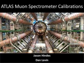
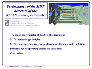
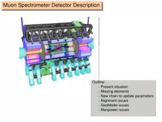
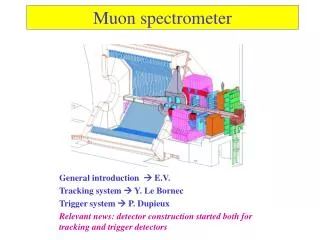
Muon Spectrometer Instrumentation • High resolution and highacceptance MUONmeas. • by measuring P using an Air-Core Toroid, • with rapidity coverage up to 2.7. • To track MUON’s with a precision similar or better than the Inner Detector (ID), one needs: • Precision detectors, with deformations that can be followed (MDT-CSC) • Precise mapping of the magnetic field • Alignment system over large distances, to know relative position of tracking chambers to within 30-40 microns. • To trigger on MUON’s, one needs: • Fast detectors (RPC-TGC) to provide moderate Pt measurement and Bunch ID. • Azimuthal coordinate measurement for both, MUON tracking and to provide corrections to main tracking detectors The Muon Spectrometer is instrumented with precision chambers and fast trigger chambers A crucial component to reach the required accuracy is the sophisticated alignment measurement and monitoring system
Axial lines (RASNIK) Projective lines (RASNIK) MUON Spectrometer • Intrinsic resolution of chambers+ alignment dominant for P>300GeV/c. With the specs. DP/P~10% at 1TeV. This has impact for high m(H/A) and Z’. • To achieve it, one needs: • Single point measurement with 80 microns precision (shown via chamber scan in tomograph, where 1/8 of the detectors were tested) • Parallelism between layers of 2mrad. • Follow relative movements between planes to 30-40 microns (through axial and projective alignment; shown in test beam via system test). • Known global coordinate to within 0.5mm (reference alignment system) • Know the magnetic field map. This requires over 1000 probes, located on chambers.
Barrel Muon Stations • Precision chambers are (mainly) Al-Monitored Drift Tubes • Hit resolution • Average ~80mm • 6/8 layers per station ~40mm • Align 3-stations (up to 10m) at ~40mm • Basic tracking elements are Drift-Tubes, where the wire is placed to within 10 microns; tube assembly is placed to within 20 microns, and deformation of the assembly is followed with a local alignment system.
Where are the chambers and how much do they deform • 6,000 images in the barrel and 6,000 in the end-caps. • System allows to measure: • Translations in X-Y • Rotation • magnification
2009 first look at the alignment withlatest improvement to be shown afterlong runs without magnetic field • By comparing track intersection in middle layer with expected chamber position after alignment, one can check the quality of the alignment: • For the End-Caps, one obtains that the distribution are centered at 40 microns. • For the large Barrel chambers, using tracks and making corrections with the alignment system one obtains 50 microns for the large chambers, while for the Small chambers (no direct projective lines), one needed real data with straight tracks (no magnetic field). • These runs were performed during 2010-2011, leading to major improvements in resolution. And of the MDT ATLAS
Additional element to improve alignment between sectors: use their overlap
P resolution: MS F (1/4) BL (Tm) Coils • Bending power: designed to keep constant PTresolution for rapidity less than 1 • 2-9 Tm • Small region BL~0 ! 4th station layer installed (BEE) • Material distribution • Range 1-8 √X/X0 • Hit resolution • Average ~80mm • 6/8 layers per station ~40mm • Align 3-stations (up to 10m) at ~40mm Small Sectors Small Sectors Coils Large Sectors Large Sectors Feet h
During installation, 4 coils were reconstructed in shape with very small residuals • If you know (alignment) where the chambers are, the field reconstruction works.
Toroid Field Map • Global P scale sensitive to B checked with M(Z) mean: • P scale known atbetter than 1% • MuonSpectrometer (MS) and InnerDetector (ID) measurements can be compared to check relative P scale • <(PMS – PID)>/PIDsensitive to differences in P scale, hence to B-field integralsof the 2 detectors • Alignment effect at first order cancels out since they have opposite impact on m+ and m- • Different granularity and symmetries in the 2 magnetic fields: single solenoid in the ID 3 separate Toroids in MS • For Computing reason approximate symmetric B-field map used for Toroids: in first data taking period • known to be wrong mainly due to sizable shifts of the 2 EC Toroids in Z
Effect of End-Cap Toroid shift Symmetric Toroid Field Map Asymmetric Toroid Field Map • Mean[(PMS-PID)/PID] vsh and f • Main problem was due to small longitudinal shift of one End-Cap Toroid, which was corrected in analysis. f f
Efficiency from Tag-and-Probe ? • Efficiency: Tag-and-Probe with J/Yand Z events • Tag: CBisolatedmuon Trigger + ID + MS tracks • Probe: MS OR ID tracks that is consistent with J/Y(low PT)or Z mass -we can use the same method for other variable like isolation
Tag-and-probe from Z Services MS or TAG ComBined (CB) MS+ID Inefficiency at h~0 can be recovered with calorimetric-tag muons MC reproduces data within 1% ID
Muon Resolution at high P 2011 • From these two methods constrains on the alignment contribution to P resolution derived • difference between the two estimates taken as systematic error • GOOD enough for high-PT physics Quite close to design value 40 mm 0.08 TeV-1:
Trigger is a crucial element in LHC Physics • The MUON trigger philosophy is based on opening a cone (which defines a given p(t) threshold) around a point in a pivot plane (that contains non-overlapping geometry). • The barrel includes a a 3-out-of-4 trigger logic for low p(t), combined with a 1-out-of-2 confirmation logic for high p(t) • The end-cap requires a 3-out-of-4 logic combined with a 2-out-of-3 logic in the inner layer. The low p(t) is obtained by a non-linear combination in the inner layer, while linear for the high p(t) • The end-cap has a more robust logic, due to the higher background conditions, combined with the fact that the stations are located in a non-magnetic region.
Muon trigger • 1st Level (2 ms) 40MHz 75 KHz • On chamber trigger matrix performs time coincidence of signals in trigger roads: • Low Pt Barrel 6 GeV ~ 25 cm (8 strips) • High Pt Barrel 20 GeV ~30 cm (10 Strips) • From hits time: Choose collision BX • RPC and TGC have good time resolution: BX efficiency > 99% • 2nd Level (10 ms): 3 KHz • Look to ID + MS tracks in ROI • Better Pt resolution: sharpen threshold • 3rd Level-EF (few s): 200 Hz • Full detector granularity • Offline Reconstruction Software • Sharp P threshold and Calorimetric isolation
RPC Trigger Chambers • More than 97% of the RPC towers are fully operational • Efficiency of individual layers and of coincidence is reaching its expected level. • Good matching between tracking and trigger chambers for finding the tracks.
End-Cap MUON TRIGGER SECTORS All 6 Big-Wheels that constitute the MUON Trigger System in the End-Cap (4000 detectors) Trigger efficiency for full system 94%.
Status of TGC Trigger Chambers • All TGC detectors have been timed-in for collisions. • The efficiency for each individual plane is as expected for cosmics. Although without final TGC alignment, matching with MDT tracks is excellent and allows to find the supports of the chambers. • 0.03% of noisy channels and 2.0% of problematic planes (largely fixed during shut-down).
MUONs are measured in ATLAS by 2 different detectors (Muon Spectrometer: MS); Inner Detector (ID) and combining the two measurements (CB), taking into account the energy loss in the calorimeters. Z’/W’ |h|~2 Z’/W’ |h|~0.4 ID ID MS Z/W/H Z/W/H B-phys MS B-phys CB CB Barrel: MS needed at very high Pt IDbetter up to Pt~80 GeV Endcap: IDbetter up to Pt~20 GeV MSas Barrel up to |h|~2.7 thanks to forward TOROID’s BEST resolution over full Pt and h range CB
Muon Resolution on MC • Realistic Performance: Smearing function from Data applied to MCMS • K1MS = “multiple scattering” term from a fit to M(Z) measured with MS-SA • KsMS= from alignment and hit resolution studies • ID • K2ID = ID “intrinsic term” from a fit to M(Z) measured with ID • K1ID= ID “multiple scattering” term from J/yand Ks mass studies Before Smearing After Smearing
Some examples of searches using High Pt µ’sZ’ and Higgs->4 leptons • Many SM extension foresee heavy Z bosons (e.g., Sequential Standard Model, E6 GUT theory,..) • Data Analysis based on: • ee final state: require GOOD ID and calo1.08 fb-1 • m+m- final states: require GOOD ID and MS 1.21 fb-1 • Single-e or Single-mtriggerrequired: • Thresholds 20 and 22 GeV • Trigger efficiency measured with tag-and-probe • Efficiency w.r.t. offline selection e channel: (100±0.2)% • Efficiencyw.r.t. offline selection mchannel: (98.2±0.3)%
Z’ search di-lepton mass • Compatibility of observed mass spectra with “background-only” hypothesis in different Z’ mass ranges tested: • P-values are 24% foreeand 54% formmchannels: No significant signal found
H ZZ* 4 leptons • GOLDEN channel mass above 130 GeV • Small sxBR (~3-6 fb) but also small BKG • Narrow mass peak in 4l final state • Crucial lepton efficiency • Significance ~ S/√B ~ el2 • Main backgrounds: • ZZ* 4l“irreducible”: it contains 4 prompt leptons • “Reducible” backgrounds: only 2 leptons are “prompt” • tt WbWbwith 2l from W’s and 2l from b-decays • Z-jet with Z 2lplus 2l from b/c-decays (dominant for m) or mis-identified hadrons in light flavor jets
Higgs to 4 muon Data Candidate M = 143.5 GeV M12 = 90.6 GeV M34 = 47.4 GeV
Conclusions • The ATLAS Muon Spectrometer is reaching is designed performance (due to an enormous effort throughout the last 2 years). • The performance is such that one can obtain a momentum resolution similar to the simulated one, and produce very stringent limits (measurements) relevant for high mass Z’ and Higgs searches. • Further improvements to the performance of the present detector will be very hard to achieve and will need the future detector upgrades.