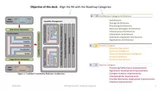
TMS320C6000 Architecture
TMS320C6000 Architecture. 1. TMS320C6000 Devices. VelociTi architecture Advanced VLIW (Very long Instruction Word) 한 사이클 (cycle) 에 8 개 32-bit instruction 을 실행 Core 는 32bit-word length 로 구성된 A, B 의 2 개의 범용 레지스터 파일과 8 Functional Unit 으로 구성 2 Multipliers / 6 Arithmetic logic units (ALUs)

TMS320C6000 Architecture
E N D
Presentation Transcript
1. TMS320C6000 Devices • VelociTi architecture • Advanced VLIW (Very long Instruction Word) • 한 사이클(cycle) 에 8개 32-bit instruction을 실행 • Core는 32bit-word length로 구성된 A, B의 2개의 범용 레지스터 파일과 8 Functional Unit으로 구성 • 2 Multipliers / 6 Arithmetic logic units (ALUs) • Instruction packing • Conditional execution of all instructions • Efficient code execution on independent functional units
8/16/32-bit data support, providing efficient memory support for a variety of applications • Hardware support for IEEE single-precision (32–bit) and double-precision (64–bit) instructions (C67x only) • 32 x 32–bit integer multiply with 32– or 64–bit result • Pin-compatible fixed-point and floating-point DSPs
2. CPU Core • 명령 Fetch 등의 명령 조작을 하는 부분 • 명령 Fetch에서는 8 명령 (32bit wide)을 하나로 모은 256bit wide의 Fetch packet을 메모리로부터 읽는다. • 계속하여 명령 Dispatch에서는 명령 구분 정보를 이용하여, 동시에 실행하도록 지정되어 있는 명령을 모아서 실행 패킷을 구성하고, 그것을 사이클마다 순서대로 명령 Decode부로 전송. • 명령 Decode부에서는 수취한 실행 패킷을 대응하는 기능유닛으로 송출
데이터 처리의 중심이 되는 데이터 패스 • Function Unit 과 범용 레지스터 파일 • Two general-purpose register files (A and B) • Two load-from-memory paths (LD1 and LD2) • Two store-to-memory paths (ST1 and ST2) • Two register file cross paths (1X and 2X) • Two data address paths (DA1 and DA2) • Eight functional units (.L1, .L2, .S1, .S2, .M1, .M2, .D1, and .D2) • .M unit : multiplication operation • .L unit : logical and arithmetic operation • .S unit : branch, bit manipulation and arithmetic operation • .D unit : loading, storing, arithmetic operation
제어 레지스터 • Addressing mode register (AMR) • Control status register (CSR) • Interrupt register (IFR, ISR, ICR, IER, ISTP, IRP, NRP) • Program counter, E1 phase (PCE1) • 이들 레지스터에 대한 엑세스에는 .S2 유닛만 관여
3. Advanced VLIW • Advanced VLIW 아키텍처에서는 A~H의 8개의 명령을 하나의 Fetch packet에 모으고, 실행단계에서 그것을 여러 개의 실행 패킷에 나누어 좌측 실행 패킷부터 순서대로 실행 • 실행 패킷이 Fetch packet에 다 들어가지 않는 경우에는 NOP명령을 삽입 • Fetch packet 구성을 보면 하나의 명령에 32비트를 할당하고, 그 중의 LSB에는 Dispatch할 때에 명령을 어디서 구분지을 것인가에 대한 정보가 들어간다. • 여러 개의 기능 유니트들을 효율적으로 이용할 수 있도록 컴파일러가 서로 다른 유니트를 사용하는 명령어들을 찾아서 하나의 명령어 단어 내에 재배열 해준다.
4. TMS320C6000 Memory • Internal data/program memory • Internal peripherals • External memory accessed through the external memory interface (EMIF).
4.1 Program Memory Controller • Performs CPU and DMA requests to internal program memory and the necessary arbitration • Performs CPU requests to external memory through the external memory interface (EMIF) • Manages the internal program memory when it is configured as cache.
4.2 Internal Program Memory Modes • CPU control and status register(CSR)의 Program cache control(PCC) field(bits 7-5)에 의해서 선택된다. • Mapped : Cache disabled (default state at reset) • Cache enabled : Cache accessed and updated on reads • Cache freeze : Cache accessed but updated on reads • Cache bypass : Cache not accessed or updated on reads
4.3 Data Memory Access • The data memory controller services all CPU and DMA controller data requests to internal data memory. • The CPU requests data reads and writes to: • Internal data memory • On-chip peripherals through the peripheral bus controller • EMIF • The DMA controller requests reads and writes to internal data memory. • The CPU cannot access internal program memory through the data memory controller.
5. Addressing mode • RISC 방식의 CPU와 같은 Load/Save Architecture • Load / Save 명령으로 메모리의 데이터에 Access • 범용 레지스터 간에 연산 • Load / Save 명령만 어드레싱 모드와 관계 • 어드레싱 모드는 어드레스를 나타내는 레지스터로서 범용 레지스터를 사용하는 간접어드레스만 지원 • Linear addressing mode와 Circular addressing mode • 두 모드의 전환은 AMR에서 이루어지고 레지스터마다 설정 가능. 단, 전환 가능한 레지스터는 A4~A7, B4~B7의 8개 레지스터 뿐이고 다른 범용 레지스터는 항상 Linear addressing mode에 대응.
Circular addressing mode란, 예를 들면 어드레스를 점점 증가시켜 가다가 정해진 영역의 마지막에 도달하면 다음에는 다시 영역의 맨 처음 어드레스로 돌아가는 모드 • Circular addressing mode는 링 버퍼(ring buffer)를 실현할 경우에 유용한 모드입니다. Circular addressing mode 일 때 영역의 크기는 Block size라 부르고 AMR에 따라 2^N(N=1, 2, 3,…, 32) 의 32가지로 설정가능
6. Fixed Point / Floating Point • Fixed point • 정수형 변수를 이용 • 사용 변수의 타입/변수의 길이(Resolution)에 중점 • 시스템이 지원하는 정수형 변수만 사용 • H/W에서는 Resolution이 최소가 되는 것에 중점 • S/W에서는 시스템, 프로그램 특성에 중점
Floating point • Floating processor는 칩 내부에서 소수 표현이 가능한 회로를 가지고 있다. • Floating point processor끼리 데이터를 주고 받는 경우, Sign bit, Exponent field, Fraction(mantissa) field가 서로 맞지 않으면 데이터 교환에 어려움이 있다. 이를 위한 규격이 Single precision, Double precision이다. • Dynamic Range가 넓고, Resolution도 크다.
6.1 Q-Math(Fixed/Fractional) • Q3.12 Format • The approximate allowable range of numbers in Q.3.12 representation is (−8,8) and the finest fractional resolution is 2^−12 = 2.441 × 10^−4. • Q15 Format • The approximate allowable range of numbers in Q.15 representation is (−1,1) and the finest fractional resolution is 2^−15 = 3.05 × 10^−5. • Q31 Format
6.2 Single-Precision Format • normalized (e is between 0 and 255) and denormalized (e is 0). • Normalized: −1s × 2^(e−127) × 1.f ; 0 < e < 255 • Denormalized (Subnormal): −1s × 2^−126 × 0.f ; e = 0; f nonzero
6.3 Double-Precision Format • normalized (e is between 0 and 2047) and denormalized (e is 0). • Normalized: −1s × 2^(e−1023) × 1.f ; 0 < e < 2047 • Denormalized (Subnormal): −1s × 2^−1022 × 0.f ; e = 0; f nonzero
Pipeline Block Diagram
7.1 Software Pipeline • 루프처리에서 복수의 기능 유닛이 독립처리를 하고, 게다가 병렬로 실행할 수 있는 경우에 소프트웨어 파이프라인은 처리를 고속화시킬 수 있는 유효한 방법 • 어셈블리 언어 레벨에서 소스코드를 기술할 경우는 소프트웨어 파이프라인 처리를 하므로 사용자가 소스 코드를 기술할 필요가 없다. 그래서 리니어 어셈블리 또는 C 언어 레벨에서 소스 코드를 기술하는 경우, 최적화 레벨을 2이상으로 하면 Assembly Optimizer나 C Compiler에 의해 자동적으로 Software Pipeline 된다. 그 때문에 사용자가 Software Pipeline을 위해 특별한 기술을 할 필요가 없다.
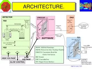
RESET RESET NMI IFR NMIE NMI IMH/L IFR NMIE IER GIE INT4-15 INT 외부 요인 EXT_INT4, 5, 6, 7 INT 내부 요인 TIMER, McBSP, EDMA(EMA), HPI, EMIF SDRAM TIMER 8. Interrupt Interrupt Priority
8.1 Interrupt register • IMH/IML(Interrupt Multiplexer High/Low register) : 인터럽트 요인을 CPU인터럽트에 매핑하기 위한 레지스터 • IFR(Interrupt Flag Register) : INT4~15, NMI의 각 인터럽트 상태를 유지한다. 인터럽트가 발생하면 1로 셋팅. • NMIE(Non-Maskable Interrupt Enable bit) : IER의 제 1 비트. 이 비트가 0이면 Non-Maskable Interrupt와 Maskable Interrupt는 금지된다. 이 비트는 일단 1로 셋팅되면 이후에는 0으로 리셋할 수 없다.
IER(Interrupt Enable Register) : 1로 셋팅하면 대응하는 인터럽트가 허가된다. • GIE(Global Interrupt Enable bit) : CSR의 제 0비트. 이 비트를 1로 셋팅하면, Maskable interrupt가 허가된다. • IFR, IER, CSR 은 CPU 코어에 포함된 제어레지스터, IMH, IML은 메모리 공간에 매핑되어있는 레지스터
8.2 Reset • Reset Reset is the highest priority interrupt and is used to halt the CPU and return it to a known state. • RESET is an active-low signal. All other interrupts are active-high signals. • RESET must be held low for 10 clock cycles before it goes high again to reinitialize the CPU properly. • The instruction execution in progress is aborted and all registers are returned to their default states. • The reset interrupt service fetch packet must be located at address 0. • RESET is not affected by branches.
8.3 Interrupt Service Fetch Packet (ISFP) • An ISFP is a fetch packet used to service an interrupt. • ISFP that contains an interrupt service routine small enough to fit in a single fetch packet (FP).
8.4 Interrupt Selector and External Interrupts • The C6000 DSP peripheral set has up to 32 interrupt sources. The CPU however has 12 interrupts available for use. • The interrupt selector allows you to choose and prioritize which 12 of the 32 your system needs to use. The interrupt selector also allows you to effectively change the polarity of external interrupt inputs
9. Peripherals • External memory interface (EMIF) • Direct-memory access (DMA) controller • Host-port interface (HPI) • Power-down logic • Two multichannel Buffered serial ports (McBSPs) • Two 32-bit timers
9.1 McBSP • McBSP : Multi channel Buffered Serial Port • 동기식 시리얼 포트 • Full-Duplex 통신 • T1/E1 framer, MVIP 스위칭 호환 장치, AC-97 호환장치, IIS 호환 장치 등에 직접 연결 • 최대 128 채널까지 다중 채널 지원 • 데이터 사이즈는 8, 12, 16, 20, 24, 32의 각 비트 폭에 대응 • PCM 데이터의 압축/신장 규격인 u-law(일본, 미국의 표준), A-Law(유럽 규격)에도 대응 • 프로그램 가능한 내부 비트 클럭 및 프레임 동기 생성기
9.2 EMIF • External Memory Interface • EMIF는 데이터 폭 32비트로 구성 • 16/8 비트 폭의 메모리도 접속 가능 • 동기 메모리인 SDRAM, SBSRAM, 비동기 메모리인 SRAM, ROM 등을 접속 • 그 외에 병렬 I/O 포트도 이 외부 메모리 인터페이스를 사용
9.3 Timer • 2개의 32비트 타이머 내장 • Time events • Count events • Generate pulses • Interrupt the CPU • Send synchronization events to the DMA controller • The timer has two signaling modes and can be clocked by an internal or an external source.
9.5 HPI (Host Port Interface) • HPI는 Host Processor와 병렬로 데이터를 주고 받을 수 있는 일종의 병렬 포트이다. DSP는 Slave로 동작하기 때문에 Data의 전송을 주도할 수 없다. • Host Processor는 DSP 프로세서의 동작에 최소한의 영향을 주면서 DSP 프로세서의 내부 및 외부 메모리를 엑세스 할 수 있다. • HPI address register(HPIA) : 호스트만이 액세스한다. 호스트가 액세스하는 HPI RAM의 어드레스를 세트한다. • HPI Control register(HPIC) : 호스트, C54x 쌍방이 액세스한다. HPI를 위한 제어 및 status bit가 포함된다. • HPI Data register(HPID) : 호스트만이 액세스한다. 호스트는 이 레지스터를 통하여,HPI RAM에의 액세스를 한다.
9.6 DMA(Direct Memory Access) • DMA는 데이터의 이동을 담당하는 유닛 • CPU 역시 데이터 이동에 관여할 수 있으나 DMA덕분에 CPU는 연산 부분에만 집중할 수 있다. • 음성이나 오디오 신호처리의 경우처럼 데이터가 빠른 속도로 스트림의 형태로 입력되거나, 비디오 신호처리 처럼 방대한 양의 데이터를 메모리로부터 읽거나 쓸 경우, DMA는 DSP가 제 성능을 발휘하는데 있어서 매우 중요한 역할을 한다.
CPU와 독립적으로 동작함 • 우선권(Priority) 설정이 가능한 6개의 DMA 채널 지원 • 각 DMA 채널은 개별적으로 CPU에 인터럽트를 발생시킬 수 있음 • 채널마다 독립적으로 Byte, Halfword, Word의 전송 크기 설정 가능 • Autoinitialization • Multi-frame transfer • Programmable address generation
TMS320C6201/C6701/C6202 (1.8V devices) DMA Structure The DMA has four independently programmable channels allowing four different contexts for operation. In addition, a fifth (auxiliary) channel allows the DMA to service requests from the host-port interface (HPI) or the Expansion Bus (XB).
CCS와 프로그램 개발 • CCS에 따른 프로그램 개발 언어 • C/C++ • Assembly • Linear Assembly • TMS320C6x의 C 컴파일러는 효율적인 실행코드를 생성하기 위해 높은 레벨의 최적화를 실행. 더욱이 DSP가 가지고 있는 특유의 기능을 이용하여 고속처리를 할 수 있는 체제로서, Intrinsics 함수를 제공한다. • Intrinsics 함수를 사용하면, 통상 C 언어로 기술하면 몇 행이나 되는 처리를 대부분의 경우 한 가지 어셈블리 명령으로 치환 가능하여 처리의 고속화에 도움을 준다. Intrinsics 함수에는 포화처리 산술연산, Halfword 길이의 두 데이터에 대한 독립된 가감승산, 비트 조작 등이 있다.
통상적으로 C 언어만을 이용하여 초고속 소프트웨어를 개발할 수 있다. • (TI사에 의하면 Assembly 언어로 작성된 경우의 60~80% 정도의 실행 속도를 달성할 수 있다고 한다.) • 그러나 고속화가 충분하지 않은 경우나 인터럽트 벡터에 관한 기술을 할 경우에는 리니어 어셈블리 언어를 사용한다
Code Optimize • Phase 1 : Develop C code • Compile and Propile native C/C++ code • Determines which loops are most important in terms of MIPS requirement • Phase 2 : Refine C code • Add restrict qualifier, loop iteration count, memory bank, and data alignment • Optimize C code using other C6000 intrinsics and other methods • Phase 3 : Write Linear Assembly • Write linear assembly • Add partitioning information to the linear assembly