Introduction to Object-Oriented Design Concepts
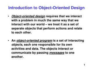
Introduction to Object-Oriented Design Concepts. Object-Oriented Design Overview. Object-Oriented design is basically a set of guidelines/concepts for developing software that is bug free and easily maintained. Object-oriented vs. Procedural. Procedural

Introduction to Object-Oriented Design Concepts
E N D
Presentation Transcript
Object-Oriented Design Overview • Object-Oriented design is basically a set of guidelines/concepts for developing software that is bug free and easily maintained
Object-oriented vs. Procedural • Procedural • Programmer is dependent on language-defined data types (primitives) • C offers the struct concept to create compound data types but no way to create operators that work on those user defined types • For function calls data must be passed in via argument lists or globally scoped variables
Object-oriented vs. Procedural • Object-oriented • Programmer can create their own data types • In some languages (e.g. C++) the programmer can define operators to work on the defined data types • There are no function calls • Object methods are activated via message passing • Data can be passed via • Argument list • Globally scoped variables • Receiver scoped variables
Objects • In an Object-Oriented design, attributes and behaviors are grouped together into a single container • Attributes are data items (member variables) • Behaviors are methods (member functions) • The container is the class • Avoid global data and functions • Data and functions that are declared outside any class • Some OO languages do not even allow this (Java)
Data Hiding • Access to class methods and attributes should be restricted • Attributes should be private • Access to attributes is provided by • Accessors (“getters”) • Mutators (“setters”) • Behaviors may be public or private, depending on their functionality • Public methods are message handlers • Only the interface is exposed to the “outside world” • Implementation details are hidden • Private methods are helpers • Existence is completely withheld from the “outside world”
Class and Object • A class is a high-level data item (abstract data type) that will be useful in designing your software but not supplied natively by the language • A class has no physical existence • Objects are the data items instantiated (declared) of type class • An object has a physical existence in computer memory
Attributes • Can be native (primitive) data types (int, double, float, char, …) • Can be abstract data types (class) • Should be private
Methods • Constructors – for initialization of the newly instantiated object • Destructor (C++) – for clean-up of an unneeded object (finalize in Java) • Message handlers – publicly accessible for communication among objects • Helpers – private functions for use within the object
Encapsulation • Interface • The type-signature of the message handlers • Name, argument types, return type • May be a language specific construct as in Java • May be a header file as in C++ • VB??? C#??? • Implementation • The code that performs the desired task • Hidden from the outside world
Composition/Aggregation • A form of code reuse • Break a large object into small objects that may be useful in other places • Easier to • Understand • Design • Implement • Debug • The “has-a” test is used to determine if an aggregation relationship between two classes is appropriate
Inheritance • Another form of code reuse • Grouping of attributes and behaviors that are common to two or more classes • The common attributes/behaviors are formed into a class called the base class, super class, or parent class • New classes may extend the base class to include additional functionality not common to other classes • Called the Derived class, sub-class, or child class • The “is-a” test is used to determine if an inheritance relationship between two classes is appropriate
Inheritance • An inheritance tree or inheritance hierarchy is formed by deriving new classes from the previously derived classes – all with heritage (ancestry) back to the root class • Some languages (C++) allow for multiple inheritance – Java does not [directly] • What problems arise with multiple inheritance?
Polymorphism • A single message that can be handled by anyone of a number of message handlers • The specific message handler is determined by the context of the message • The determination is made at run time (unless the compiler can do it based on the type-signature of the message) • Inheritance relationships can cause confusion • Object-oriented languages usually offer some form of real-time-type-identification (RTTI)
Object-Oriented Design Process(actually, all design processes) • Conceptualization • Analyze the problem specification • Identify primary classes and their relationships • Representation • Model the system • Refine classes (change, add, delete) • Implementation • Convert the model to code
Conceptualization • Make sure you understand the given task before you start working on it • Read the specification • Ask the customer/user questions • Create informal scenarios • Identify useful classes/objects • Clear up any ambiguities that may exist • Create UML Use Case diagrams • Identify test cases to validate proper system operation • Present your understanding to the team (informal walk-thru) and to the customer (structured walk-thru)
Representation • Create a model of the system • Unified Modeling Language • Class diagrams • Interaction diagrams • Sequence • Collaboration (Communication) • State diagrams • Deployment diagrams • Others as necessary • Code prototypes • How detailed should the UML be? • Sketch • Blueprint • Programming Language
Implementation • Convert models (UML diagrams) to code • Class skeletons • Method signatures • Pseudo code (comments) • Operational programs
Use Case Diagram Chapter 9
Informal Scenario • When there are parts of the system… • …that you just don’t understand by reading the specification… • …that are obvious from reading the specification… • …you should “play computer” • This is what informal scenarios are for
Informal Scenario • Describe in excruciating detail, exactly how the system (hardware + software + user) operates under various conditions • Cover a very small “snippet” of the system operation • They are not beginning-to-end descriptions! • If you make enough informal scenarios, you could conceivably link them together to make a beginning-to-end description
X O X O X O X O O Informal Scenario • Consider a tic-tac-toe game Title: End-Game Current State: X has markers in the upper-left and right squares O has markers in the upper and middle-middle squares It is O’s turn Scenario: O places a marker the lower-middle square Seeing that O has three of its markers unblocked, horizontally, in the middle column O declares itself the winner X concedes defeat Next Scenario(s): 1) Request rematch 2) Throw tantrum
Informal Scenario • Guidelines • Should be short • Should address only one system activity • Should utilize specific/concrete values • Should address pass (expected behaviors) and fail (unexpected behaviors) situations • Should not contain implementation details • Should describe the state of the system going into the scenario • Should indicate the next scenario(s)
Informal Scenario • Bad scenario: Title: End-Game Current State: X has two markers on the board O has two markers on the board Scenario: O places another marker on the board O declares itself the winner because it has three markers in a row Next Scenario(s): 1) Request rematch 2) Throw tantrum
Scenario • A scenario is a sequence of informal scenarios chained together to describe an end-to-end behavior of the system • Note that depending on how informal scenarios are chained together, multiple scenarios can be created
Use Case • Capture the functional requirements of a system • Describe typical interactions between the users and the system • Users may be people, data sources, or other systems • Represent a set of scenarios that are of similar functionality (but may differ in their detail)
UML • Does not provide any diagrams or guidelines for developing informal scenarios or scenarios • Does provide facilities for creating use case diagrams
Use Case Diagram System boundary Use cases Actor Actor Use cases
Use Case Diagram • It’s merely a graphical representation of the functions performed by the system • Don’t try to add a lot of detail to them, just capture the essence of the system functionality • Detail will come in later diagrams • You can think of the Use Case Diagram as a “table of contents” and the other diagrams to be the “content”
Project Deliverables • Write a formal specification document including my functional specifications and the answers I gave to your questions • Due next class meeting (Deliverables continued on next page)
Project Deliverables • Create informal scenarios • Create scenarios • Create a use case diagram • Note that this is probably a very simple diagram since we are designing a very simple system • Due week after next (I want to see progress next week and answer any questions you may have)