
Heat Engine
E N D
Presentation Transcript
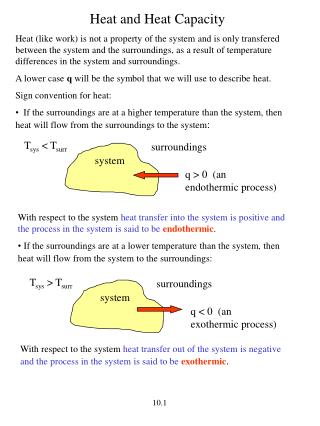
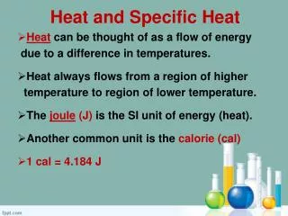
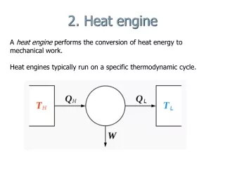
Heat Engine In engineering and thermodynamics, a heat engine performs the conversion of heatenergy to mechanical work by exploiting the temperature gradient between a hot "source" and a cold "sink". Heat is transferred from the source, through the "working body" of the engine, to the sink, and in this process some of the heat is converted into work by exploiting the properties of a working substance (usually a gas or liquid).
A heat engine typically uses energy provided in the form of heat to do work and then exhausts the heat which cannot be used to do work. Thermodynamics is the study of the relationships between heat and work. The first law and second law of thermodynamics constrain the operation of a heat engine. The first law is the application of conservation of energy to the system, and the second sets limits on the possible efficiency of the machine and determines the direction of energy flow.
Parts • The parts of an engine vary depending on the engine's type. For a four-stroke engine, key parts of the engine include the crankshaft (purple), one or more camshafts (red and blue) and valves. For a two-stroke engine, there may simply be an exhaust outlet and fuel inlet instead of a valve system. In both types of engines, there are one or more cylinders (grey and green) and for each cylinder there is a spark plug (darker-grey), a piston (yellow) and a crank (purple). A single sweep of the cylinder by the piston in an upward or downward motion is known as a stroke and the downward stroke that occurs directly after the air-fuel mix in the cylinder is ignited is known as a power stroke. • A Wankel engine has a triangular rotor that orbits in an epitrochoidal (figure 8 shape) chamber around an eccentric shaft. The four phases of operation (intake, compression, power, exhaust) take place in separate locations, instead of one single location as in a reciprocating engine. • A Bourke Engine uses a pair of pistons integrated to a Scotch Yoke that transmits reciprocating force through a specially designed bearing assembly to turn a crank mechanism. Intake, compression, power, and exhaust all occur in each stroke of this yoke.
Engine Cycle • Two-stroke • Engines based on the two-stroke cycle use two strokes (one up, one down) for every power stroke. Since there are no dedicated intake or exhaust strokes, alternative methods must be used to scavenge the cylinders. The most common method in spark-ignition two-strokes is to use the downward motion of the piston to pressurize fresh charge in the crankcase, which is then blown through the cylinder through ports in the cylinder walls. Spark-ignition two-strokes are small and light (for their power output), and mechanically very simple. Common applications include snowmobiles, lawnmowers, weed-whackers, chain saws, jet skis, mopeds, outboard motors and some motorcycles. Unfortunately, they are also generally louder, less efficient, and far more polluting than their four-stroke counterparts, and they do not scale well to larger sizes. Interestingly, the largest compression-ignition engines are two-strokes, and are used in some locomotives and large ships. These engines use forced induction to scavenge the cylinders.
Four-stroke • Engines based on the four-stroke cycle or Otto cycle have one power stroke for every four strokes (up-down-up-down) and are used in cars, larger boats and many light aircraft. They are generally quieter, more efficient and larger than their two-stroke counterparts. There are a number of variations of these cycles, most notably the Atkinson and Miller cycles. Most truck and automotive Diesel engines use a four-stroke cycle, but with a compression heating ignition system. This variation is called the diesel cycle.
Bourke Engine • In this engine, two diametrically opposed cylinders are linked to the crank by the crank pin that goes through the common scottish yoke. The cylinders and pistons are so constructed that there are, as in the usual two stroke cycle, two power strokes per revolution. However, unlike the common two stroke engine, the burnt gases and the incoming fresh air do not mix in the cylinders, contributing to a cleaner, more efficient operation. The scotch yoke mechanism also has low side thrust and thus greatly reduces friction between pistons and cylinder walls. The Bourke cycle's combustion phase more closely approximates constant volume combustion than either four stroke or two stroke cycles do. It also uses less moving parts, hence needs to overcome less friction than the other two reciprocating types have to. In addition, its greater expansion ratio also means more of the heat from its combustion phase is utilized than is used by either four stroke or two stroke cycles
Controlled Combustion Engine • These are also cylinder based engines may be either single or two stroke but use, instead of a crankshaft and piston rods, two gear connected, counter rotating concentric cams to convert reciprocating motion into rotary movement. These cams practically cancel out sideward forces that would otherwise be exerted on the cylinders by the pistons, greatly improving mechanical efficiency. The profiles of the cam lobes(which are always odd and at least three in number) determine the piston travel versus the torque delivered. In this engine, there are two cylinders that are 180 degrees apart for each pair of counter rotating cams. For single stroke versions, there are the same number of cycles per cylinder pair as there are lobes on each cam, twice as much for two stroke units. • Wankel • The Wankel engine operates with the same separation of phases as the four-stroke engine (but with no piston strokes, would more properly be called a four-phase engine), since the phases occur in separate locations in the engine; however like a two-stroke piston engine, it provides one power 'stroke' per revolution per rotor, giving it similar space and weight efficiency.
Gas turbine • With gas turbine cycles (notably Jet engines), rather than use the same piston to compress and then expand the gases, instead separate compressors and gas turbines are employed; giving continuous power. Essentially, the intake gas (air normally) is compressed, and then combusted with a fuel, which greatly raises the temperature and volume. The larger volume of hot gas from the combustion chamber is then fed through the gas turbine which is then easily able to power the compressor. • Disused methods • In some old non-compressing internal combustion engines: In the first part of the piston downstroke a fuel/air mixture was sucked or blown in. In the rest of the piston downstroke the inlet valve closed and the fuel/air mixture fired. In the piston upstroke the exhaust valve was open. This was an attempt at imitating the way a piston steam engine works.
Fuel and oxidizer types • Fuels used include petroleum spirit (North American term: gasoline, British term: petrol), liquified petroleum gas, vapourized petroleum gas, compressed natural gas, hydrogen, diesel fuel, jet fuel, landfill gas, biodiesel, biobutanol, peanut oil and other vegoils, bioethanol, biomethanol (methyl or wood alcohol) and other biofuels. Even fluidised metal powders and explosives have seen some use. Engines that use gases for fuel are called gas engines and those that use liquid hydrocarbons are called oil engines. However, gasoline engines are unfortunately also often colloquially referred to as 'gas engines'. • The main limitations on fuels are that the fuel must be easily transportable through the fuel system to the combustion chamber, and that the fuel release sufficient energy in the form of heat upon combustion to make use of the engine practical.
Cylinders • Internal combustion engines can contain any number of cylinders with numbers between one and twelve being common, though as many as 36 (Lycoming R-7755) have been used. Having more cylinders in an engine yields two potential benefits: First, the engine can have a larger displacement with smaller individual reciprocating masses (that is, the mass of each piston can be less) thus making a smoother running engine (since the engine tends to vibrate as a result of the pistons moving up and down). Second, with a greater displacement and more pistons, more fuel can be combusted and there can be more combustion events (that is, more power strokes) in a given period of time, meaning that such an engine can generate more torque than a similar engine with fewer cylinders. The down side to having more pistons is that, over all, the engine will tend to weigh more and tend to generate more internal friction as the greater number of pistons rub against the inside of their cylinders. This tends to decrease fuel efficiency and rob the engine of some of its power. For high performance gasoline engines using current materials and technology (such as the engines found in modern automobiles), there seems to be a break point around 10 or 12 cylinders, after which addition of cylinders becomes an overall detriment to performance and efficiency, although exceptions such as the W16 engine from Volkswagen exist.
Most car engines have four to eight cylinders, with some high performance cars having ten, twelve, or even sixteen, and some very small cars and trucks having two or three. In previous years some quite large cars, such as the DKW and Saab 92, had two cylinder, two stroke engines. • Radialaircraft engines, now obsolete, had from three to 28 cylinders, such as the Pratt & Whitney R-4360. A row contains an odd number of cylinders, so an even number indicates a two- or four-row engine. The largest of these was the Lycoming R-7755 with 36 cylinders (four rows of nine cylinders) but never entered production. • Motor cycles commonly have from one to four cylinders, with a few high performance models having six (though some 'novelties' exist with 8, 10 and 12). • Snowmobiles usually have two cylinders. Some larger (not necessarily high-performance, but also touring machines) have four. • Small portable appliances such as chainsaws, generators and domestic lawn mowers most commonly have one cylinder, although two-cylinder chainsaws exist.
Ignition System • Internal combustion engines can be classified by their ignition system. The point in the cycle at which the fuel/oxidiser mixture are ignited has a direct effect on the efficiency and output of the ICE. For a typical 4 stroke automobile engine, the burning mixture has to reach its maximum pressure when the crankshaft is 90 degrees after TDC. The speed of the flame front is directly affected by compression ratio, fuel mixture temperature and octane or cetane rating of the fuel. Modern ignition systems are designed to ignite the mixture at the right time to ensure the flame front doesn't contact the decending piston crown. If the flame front contacts the piston, pinking or knocking results. Leaner mixtures and lower mixture pressures burn more slowly requiring more advanced ignition timing. Today most engines use an electrical or compression heating system for ignition. However outside flame and hot-tube systems have been used historically. Nikola Tesla gained one of the first patents on the mechanical ignition system with U.S. Patent 609250
Fuel systems • Fuels burn faster, and more completely when they have lots of surface area in contact with oxygen. In order for an engine to work efficiently the fuel must be vaporized into the incoming air in what is commonly referred to as a fuelair mixture. There are two commonly used methods of vaporizing fuel into the air, one is the carburetor and the other is fuel injection. • Often for simpler reciprocating engines a carburetor is used to supply fuel into the cylinder. However, exact control of the correct amount of fuel supplied to the engine is impossible. Carburetors are the current most widespread fuel mixing device used in lawnmowers and other small engine applications. Prior to the mid-1980s carburetors were also common in automobiles. • Larger gasoline engines such as used in automobiles have mostly moved to fuel injection systems (see Gasoline Direct Injection). Diesel engines always use fuel injection. • LPG engines use a mix of fuel injection systems and closed loop carburetors. • Other internal combustion engines like jet engines use burners, and rocket engines use various different ideas including impinging jets, gas/liquid shear, preburners and many other ideas.
Intake. During the intake stroke, the piston moves downward, drawing a fresh charge of vaporized fuel/air mixture. The illustrated engine features a 'poppet' intake valve which is drawn open by the vacuum produced by the intake stroke. Some early engines worked this way, however most modern engines incorporate an extra cam/lifter arrangement as seen on the exhaust valve. The exhaust valve is held shut by a spring (not illustrated here).
Compression. As the piston rises the poppet valve is forced shut by the increased cylinder pressure. Flywheel momentum drives the piston upward, compressing the fuel/air mixture.
Power. At the top of the compression stroke the spark plug fires, igniting the compressed fuel. As the fuel burns it expands, driving the piston downward.
Exhaust. At the bottom of the power stroke, the exhaust valve is opened by the cam/lifter mechanism. The upward stroke of the piston drives the exhausted fuel out of the cylinder
Intake. The fuel/air mixture is first drawn into the crankcase by the vacuum created during the upward stroke of the piston. The illustrated engine features a poppet intake valve, however many engines use a rotary value incorporated into the crankshaft.
Transfer/Exhaust. Toward the end of the stroke, the piston exposes the intake port, allowing the compressed fuel/air mixture in the crankcase to escape around the piston into the main cylinder. This expels the exhaust gasses out the exhaust port, usually located on the opposite side of the cylinder. Unfortunately, some of the fresh fuel mixture is usually expelled as well.
Compression. The piston then rises, driven by flywheel momentum, and compresses the fuel mixture. (At the same time, another intake stroke is happening beneath the piston).
Power. At the top of the stroke the spark plug ignites the fuel mixture. The burning fuel expands, driving the piston downward, to complete the cycle.
Detailed Description • Fuel and oxygen are injected • Fuel and oxygen are compressed and ignited • Fuel combusts and piston is pushed downwards • Exhaust is removed